3D Scanning and Printing
This week we investigated on the scanning technologies and print 3D. I particularly focus on scanning, so here I will comment my exploration by the various techniques that I made. Laser Scanner
This week we investigated on the scanning technologies and print 3D. I particularly focus on scanning, so here I will comment my exploration by the various techniques that I made. Laser Scanner

For this technique I used a laser scanner brand "Next Engine", which was fairly intuitive. Steps: 1. We click the "scan" button that is in the menu. 2. Is not going to appear many options for scanning. Among them we have to scan in 360 degrees, scan 180 degrees or scan a part. The number of divisions, which serves to define how many sides are going to scan. We chose the accuracy and speed of scanning. Finally we can choose the conditions of the environment. An important fact is that we can select the area most important to us, drawing a square with the cursor. 3. We click "start" 4. We give you click to "fusion" and with this we get a surface resulting from the fusion of all the jacks. Observations: We have to look that the shaft of scanning by which the object will rotate, coincides with the axis of the base. The object we choose do not have to reflect much light, because that prevents scan correctly. In my first attempt the mesh was not good because the object that I chose reflected the light.
My second attempt I achieved a better definition with the object, but equally it left me many holes and meshes who were crosslinked each other.
Kinect Scanner

The Kinect is a very known camera to be launched to the market next to the console Xbox 360, later Microsoft pulled out a later version for desktop PC's and laptops. For use Kinect on our computer, we need to install its drivers from this page: Kinect SDK The software That I used to scan with Kinect, is the Skanect payment program in his free version. Skanect To used we have to do the following: 1. Click on start. 2. Click on "record" and select the "delay" before you record and the time of the grabacion. 3. Click on the button that has the icon of a circulo. 4. Move the Kinect to record the object. 5. When you have finished recording, click on "reconstruct" and subsequently in "fusion". To merge all the tomas. 6. Click on "process" to edit the mesh. With "Fill Holes" we can improve the mesh covering the holes and with "colorize" we can added colour to our model. 7. Click on "share" to export the model in OBJ, STL, VRML or PLY. Observation: The free version limits us to have a model with 5000 faces, this greatly simplifies the mesh and the exported model ceases to be good.
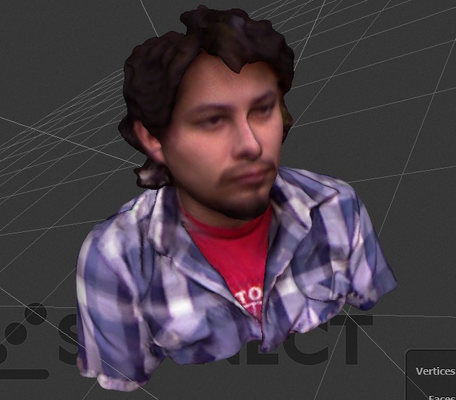
123D Catch This is a tool of Autodesk that enables us to obtain a 3D model from photos taken around an object. Its algorithm is of photogrammetry, but also produces meshes much more defined. To use it is enough go to the next page: 123D Catch How the program uses the method of photogrammetry, we need a bank of images of the object with "shots" of all the possible angles. The steps in order to obtain the mesh are easy, we load the album of images in a new project and let the software make the operation by himself generating the mesh. Finally we export the model.
In this project then to obtain the model, use Netfabb to fix the holes in the mesh. Using the option "repair" whose symbol is a cross, we achieve correct faults in the mesh. Later to improve some parts of the model, I sculpted the nose and the chin using "Sculptris", in this way, the model was ready to be printed.
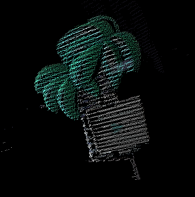
Projector Scanner For this technique I used the Three Phase program for processing of Kyle McDonald, this technique is based on using a camera and a projector. The projector is used to project lines in the object so that the camera will take pictures of the projected lines and so they will can generate in the computer the curves of the level of the object, for his subsequent reconstruction. As I was uncomfortable sending image by image, I did a sequencer of images in "Processing". Also, to take pictures of the object with the projected lines, I made a program to take screen shots using a webcam or a camera connected to the computer with a click. The program allows to display the cloud of points and export it in OBJ format, like a cloud or as mesh. The program can be found at: Three Phase Beginning with one piece molded wood in Shopbot, the result was as follows:
The following is an example of the same palm tree used previously:
Code for projecting lines
/*Using fullscreen library
if you processing version is 1.5.1

By Michael Hurtado
*/

//import fullscreen.*;
//FullScreen fs;
PImage img1,img2,img3;
int inicioLoop = 0;
void setup() {
  size(1000, 720);

  img1 = loadImage("horizontal/i1.png"); //if you can use vertical/i1.png for vertical lines
  img2 = loadImage("horizontal/i2.png");
  img3 = loadImage("horizontal/i3.png");

  //fs = new FullScreen(this);
  //fs.enter();
}
void nuevoInicio(){
  inicioLoop = millis();
}
void draw() {
  if (millis()<inicioLoop+5000){
    image(img1,0,0);
  }
  else if (millis()<inicioLoop+10000){
    image(img2,0,0);
  }
  else if (millis()<inicioLoop+15000){
    image(img3,0,0);
  }
  else{
    nuevoInicio();
  }
}
Code for take a picture with webcam
/*
This code use GSvideo library by Andres Colubri writing for Processing

Code by Michael Hurtado
*/
import codeanticode.gsvideo.*;


GSCapture cam;
int i=1;
void setup() {
  size(640, 480);

  String[] cameras = GSCapture.list();

  if (cameras.length == 0) {
    println("There are no cameras available for capture.");
    exit();
  } else {
    println("Available cameras:");
    for (int i = 0; i < cameras.length; i++) {
      println(cameras[i]);
    }
    //this is for external camera, if you using the laptop camera change 1 to 0
    cam = new GSCapture(this, width, height, cameras[1]);
    cam.start();
  }
}

void draw() {
  if (cam.available() == true) {
    cam.read();
  }
  image(cam, 0, 0);
}
void mousePressed() {
  saveFrame("phase"+i+".jpg");
  i=i+1;
}
Python Photogrammetry Toolbox Again using the technique of photogrammetry, this time i wanted to test this tool made for Python por Arc-Team. First, we need to download the program and install it according to the following link: Python Photogrammetry Toolbox For can use it we have to follow the following steps: 1. Open the GUI. 2. Click on "Check Camera Database". 3. Select the option "Select Photos Path". 4. Upload the images necessary to perform the fotogrametria. 5. Click on "run". 6. If everything is correct, we will see the following message in the terminal: Camera is already inserted into the database. If we see another message, follow the following tutorial: Tutorial 7. We copied the path. 8. Click on "Run Bundler". 9. We glued the path. 10. Select "Scale photos with a scaling factor" and click "run". 11. We now have a cloud of points, copy the directory where you saved the archivo. 12. Again in the GUI, we are going to "run or PMVS without CMVS". 13. Select "Use directly PMVS2 (without CMVS) 14. We glued the copied directory in "Select Output Path Bundler" 15. Click on "run" 16. We copied the PLY file generated in "home", since by default is generated in temporary files. Once that we already have the file as a cloud of points, we are going to Meshlab for editing. A good tutorial for this is the following link: Meshlab edition For do a test on this program, use the same model that when I used 123D catch. The differences are pretty glaring, in this second case requires too much post-production.
Micro Scanner

For this purpose I decided to scan small objects, so I used the microscope of the Fab Lab UNI. The microscope that I used is a Celestron which has a resolution of 10X to 150X. The first was seeing their approach, testing it with a few things.
It seemed to me that after my investigation, the technique of photogrammetry with 123D Cath was even better than that of Python Photogrammetry Toolbox, as it required less post-production. Then, I generated an algorithm to take images in "Processing" (is the same algorithm that I used for the web camera and the projector), so that is stored in a folder as a bank of images for later use in 123D catch. To take the images, use a rotating turntable. This made that can take pictures from a series of angles and so have better results.
My own scanner Finally I used Processing to create my own scanner 3D, using Simple OpenNI library.
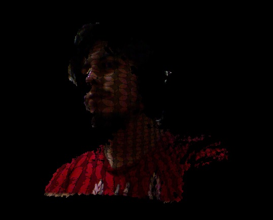
Code
import processing.opengl.*;
import SimpleOpenNI.*;

SimpleOpenNI kinect;
float        zoomF =0.6f;
float        rotX = radians(180);
float        rotY = radians(0);

void setup() {
 size(1024, 768, OPENGL);
 kinect = new SimpleOpenNI(this);
 kinect.enableDepth();
 kinect.enableRGB();
 kinect.alternativeViewPointDepthToImage();
}
void draw() {
 background(0);
 kinect.update();
 PImage rgbImage = kinect.rgbImage();

 translate(width/2, height/2, 0);
 rotateX(rotX);
 rotateY(rotY);
 scale(zoomF);

 PVector[] depthPoints = kinect.depthMapRealWorld();
 for (int i = 0; i < depthPoints.length; i+=1) {
 PVector currentPoint = depthPoints[i];
 stroke(rgbImage.pixels[i]);
 point(currentPoint.x, currentPoint.y, currentPoint.z);
 }
}

void keyPressed()
{
switch(key)
{
case ' ':
kinect.setMirror(!kinect.mirror());
break;
}
switch(keyCode)
{
case LEFT:
rotY += 0.1f;
break;
case RIGHT:
// zoom out
rotY -= 0.1f;
break;
case UP:
if (keyEvent.isShiftDown())
zoomF += 0.02f;
else
rotX += 0.1f;
break;
case DOWN:
if (keyEvent.isShiftDown())
{
zoomF -= 0.02f;
if (zoomF < 0.01)
zoomF = 0.01;
}
else
rotX -= 0.1f;
break;
case ENTER:
saveFrame("######.png");
break;
}
}
3D Printer

The other task was print an object, the printer to use is the Felix 2.0 .His software is Repetier. This printer uses a system of extrusion of filaments of PLA. The model that I printed is what I did with 123D Catch. As it was a sculpture, I gave only 10% of fill of manner that it was structural, but without so much padding to ensure that there is no delay in print. In addition, it was necessary to make two previous models, because when it have a small surface area as a basis, the headstock pull out the piece and doesn't end the print. I ended up doing 3 models, one small, other medium and another with base.
Downloading link for my archive: Archive
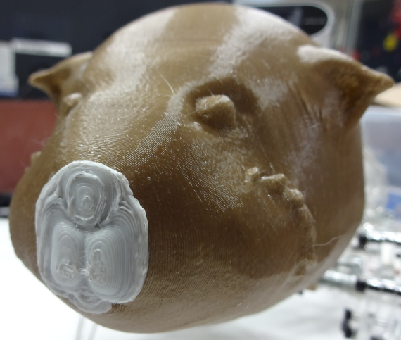
Actualization For my final project I printed the head of the guinea pig using PLA in a Makerbot. The time of de process was 20 minutes because the piece is empty.
Downloading link for my archive: Archive