For the task of this week we had to do an output devices.
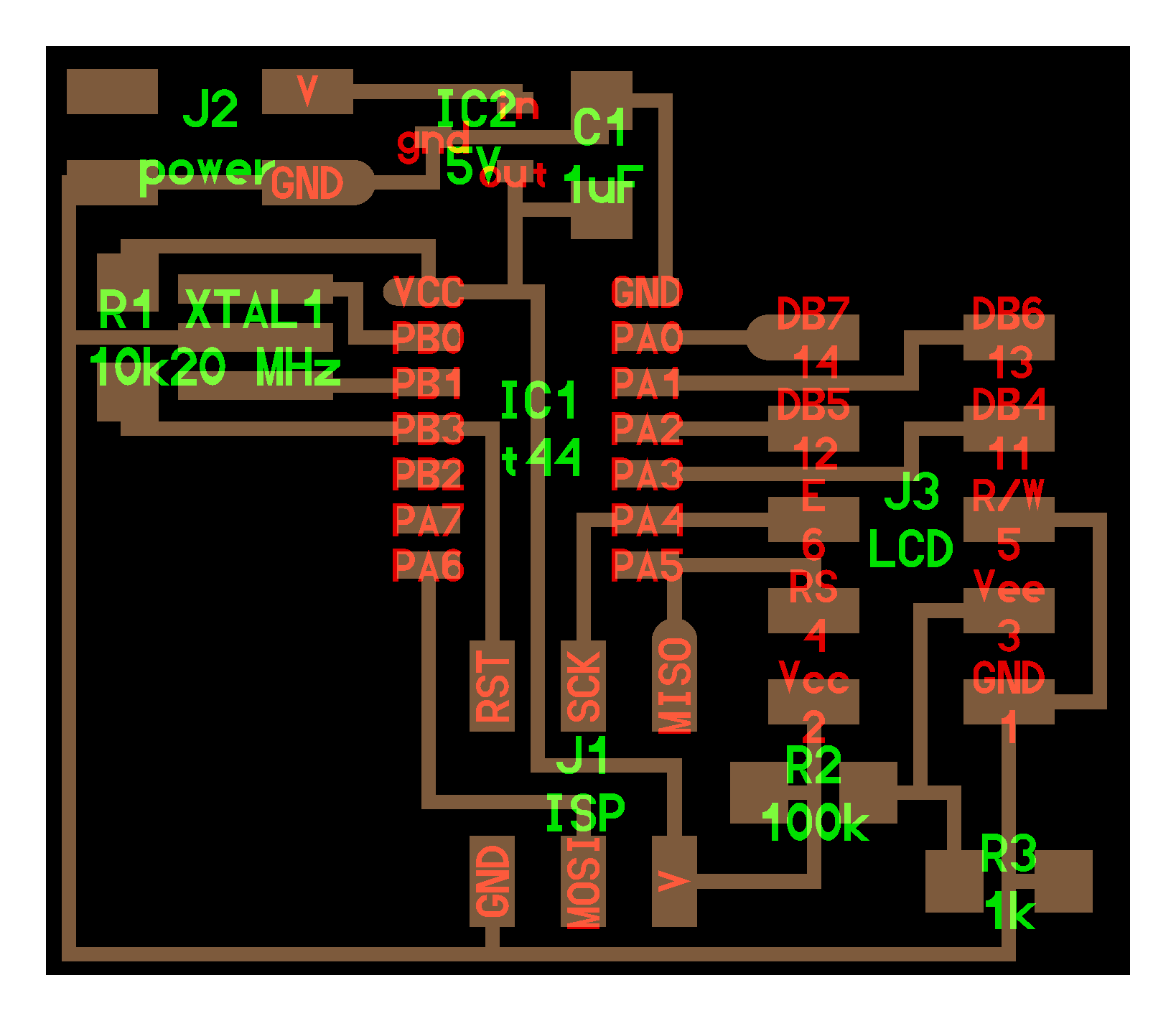
I chose the plate for the servo motor and the plate for the LCD.
Materials:
LCD:
- AtTiny44a
- A resistor of 1k Ω
- A resistor of 10k Ω
- A resistor of 100k Ω
- A 5v regulator
- A capacitor of 1uF
- A 20MHz resonator
- Headers
- An LCD
Servomotor:
- Attiny44a
- A resistor of 10k Ω
- A 5v regulator to 1 ampere
- A 22uF capacitor
- A 20MHz resonator
- Headers
- Servomotor
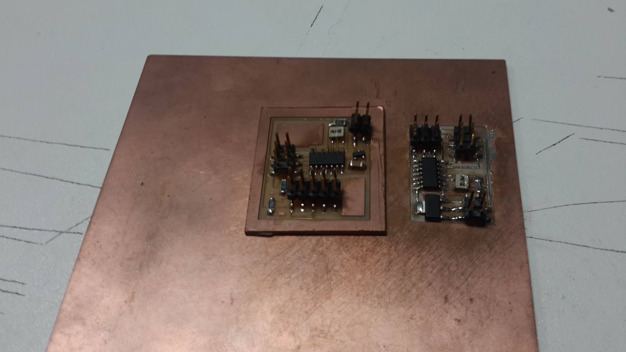
Manufacturing:
For the manufacture of boards I used:
- Copper plates
- Tweezers
- Soldering iron
- Solder paste
- Solder
- Roland Modela MDX 20
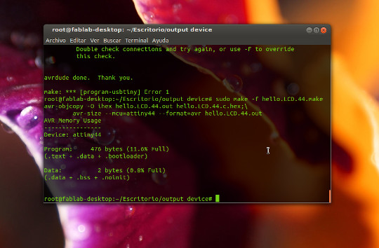
Programming:
We will do the programming of the "LCD", analogously for the servo.
We downloaded the files ".make" and ".hex" of the page for the LCD:
http://academy.cba.mit.edu/classes/output_devices/index.html
For the programming of the LCD we wrote as super user on the console the following:
Observations:
Initially I had problems with regulators, because for the "LCD" I used the 3.3v regulator that by mistake someone put in the box of 5v regulators. As these two regulators are similar with the exception of your code, the 3.3v ends in "a" and the 5v ends at "b".
For the "Stepper" also I had some initial problems, because when I used the microservo 9 gr this was stuck, this is due to the fact that the program that is by default uses signals PWM, but we need to recalculate the values for this servo.