Embedded Programming
The task this week was to read the datasheet of the Attiny44A and programming the board made in the task of electronic design with various languages. Datasheet Attiny 44A
The task this week was to read the datasheet of the Attiny44A and programming the board made in the task of electronic design with various languages. Datasheet Attiny 44A

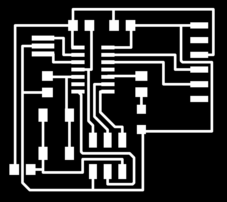
By and large we can say that this microcontroller has 8-pin for the port A and 4-pin to the port B. Alimentation of 5v, grounded and pin to reset. The pins of the ports A and B are of digital input and output, in the port A we have converters analog/digital and also they can be used as analog pins. About the task of programming, I had to design another board and fabricate because what I had made in my previous assignment did not work. I had to take this action because I made two more plates and had problems of short circuit. The new board is the following:
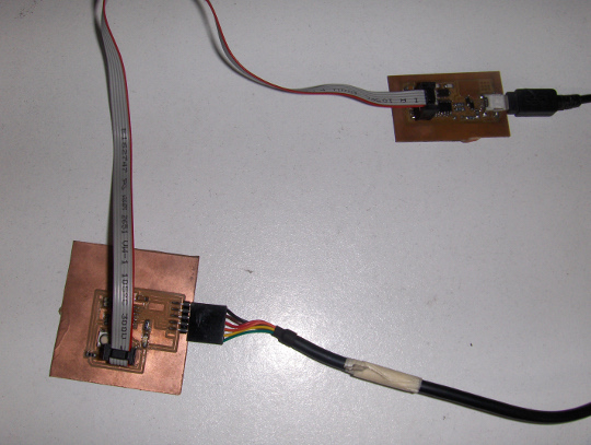
Downloading link for my archives: Archives Programming FabHello 1. We download the files hello.ftdi.44.echo.c and hello.ftdi.44.echo.c.make placing them where we want. 2. We connect the FabISP and Hello board, always taking into account the direction of MISO.
3. On the Linux terminal as an administrator, we wrote the following:
make -f hello.ftdi.44.echo.c.make
We will appear as following: 4. Now we wrote:
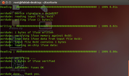
make -f hello.ftdi.44.echo.c.make program-usbtiny-fuses
We will appear the following text:
5. Also we write:
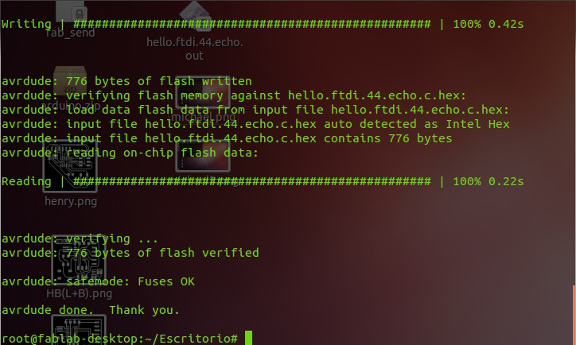
make -f hello.ftdi.44.echo.c.make program-usbtiny
We obtain:
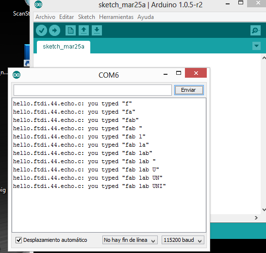
6. We open the Arduino IDE. 7. We Open the serial monitor and chose 115200 baudios. 8. We wrote a message, character by character.
Programming FabHello with Arduino IDE: 1. We downloaded and installed Arduino, for Linux there is only that enter as administrator and type "apt-get install arduino" in the terminal. 2. We download the boards files of the Attiny44 from this link: Library 3. We renamed the folder of the boards as "tiny". 4. To add the boards into the Arduino IDE we proceed as follows: In Windows We open the folder of Arduino. We opened the folder hardware. We paste the folder tiny. We opened up the IDE of Arduino and we enter a Tools/Boards to see that effectively it recognized the files added. In Linux We open the terminal and start the program Arduino, writing "arduino" in the terminal. We enter in file/preferences and localize the location of the sketchbook folder. Within the folder "sketchbook" we created the folder "hardware". We copy the folder tiny within the folder hardware. Within the folder "tiny" we created a document "boards.txt" We open the file "Prospective Boards.txt" that is within the folder "tiny" and we copy all the contents of the file to "boards.txt" We save the changes in the file "boards.txt" We open the IDE of Arduino and enter to Tools/Boards to see that actually recognized the files added. 5. To programming is necessary to revise our schematic and use the next table below to work with pins of the microcontroller:

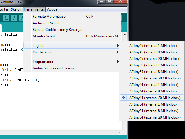
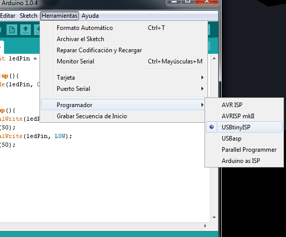
In my case I am using the pin 10 to the led and the pin 5 for the button. This in the programming translates into use the pin 3 for the led and the pin 8 for the button in the Arduino IDE. 6. Once that we already have the program, we are going to Tools/Boards to select the plate "Attiny 44 external 20 MHz clock" and we select the programmer "USBtinyISP"
7. We connect the FabISP and the FTDI cable with our FabHello. In the event that our computer does not recognize the FabISP, we download the drivers from the following link: FabISP In the event that our computer does not recognize the FTDI cable,we download the drivers from the following link: FTDI For users of Windows 8, just use the option of automatic search for the drivers of the FTDI. 8. We load the code 9. Enjoy it! For this task I decided to create three types of programs, the first is to make blink the led.
const int ledPin = 3; //led pin

void setup(){
  pinMode(ledPin, OUTPUT); //led pin is output
}

void loop(){
  digitalWrite(ledPin, HIGH); //turn led on
  delay(50);
  digitalWrite(ledPin, LOW); //turn led off
  delay(50);
}
The second is to turn on the led, only when we press the button.
const int buttonPin = 8; //button pin
const int ledPin =  3; //led pin

int buttonState = 0; //variable for the state of button

void setup(){
  pinMode(ledPin, OUTPUT); //led pin is output
  pinMode(buttonPin, INPUT); //button pin is input
}

void loop(){
  buttonState = digitalRead(buttonPin); //read the state of button
  if (buttonState == HIGH){
    digitalWrite(ledPin, HIGH); //led is on
  }
  else {
    digitalWrite(ledPin, LOW); //led is off
  }
}
The third is to turn on the led after you press the button, but studying the states of the button.
const int  buttonPin = 8;
const int ledPin = 3;

int buttonPushCounter = 0;
int buttonState = 0;
int lastButtonState = 0;

void setup(){
  pinMode(buttonPin, INPUT);
  pinMode(ledPin, OUTPUT);
}

void loop(){
  buttonState = digitalRead(buttonPin);
  if (buttonState != lastButtonState){
    if (buttonState == HIGH){
      buttonPushCounter++;
    }
    else{
    }
  }
  lastButtonState = buttonState;

  if (buttonPushCounter % 2 == 0){
    digitalWrite(ledPin, LOW);
  } else{
   digitalWrite(ledPin, HIGH);
  }

}
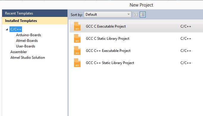
Programming FabHello with Atmel Studio For this part use the AVRISP mkII recorder and also the Atmel Studio 6.1 1. We connect the FabHello to the AVRISP to schedule it by the serial port. We must be guided of the position of the MISO in the schematic. 2. We open the Atmel Studio and create a new project "GCC C Executable Project"
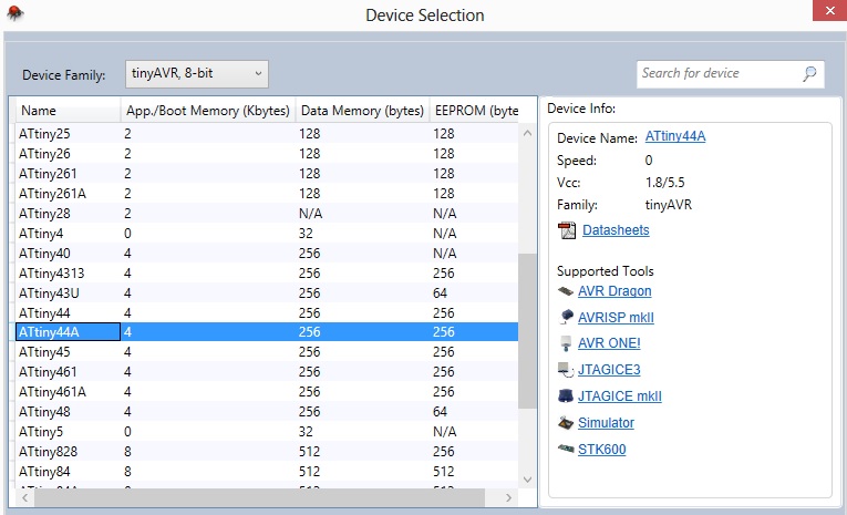
3. We select the type of microcontroller, in this case Attiny44A.
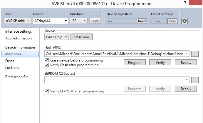
4. We programming the rutin. 5. To compile the code we pressed F5. 6. If there are no errors in the previous step, we are going to "Tools" and select "Device Programming" 7. We select in this new window the option "Tool" as "AVRISP mkII" and "Attiny44A" as device, we click into apply. 8. We select "Memories" and chose the file with extension ".hex" and finally click on "Program".
9. Enjoy it! For this task I decided to use the same types of programing that I used for Arduino, a manner to compare the differences in the employee code. Blink
#include <avr/io.h>
#include <util/delay.h>

int main(void)
{
	DDRA = 0b00001000; //0x08
	PORTA = 0b00000000;

	while(1)
	{

		PORTA = 0b00001000;
		_delay_ms(500);
		PORTA = 0b00000000;
                _delay_ms(500);

	}
	return 0;
}
Led Button
#include <avr/io.h>
#include <util/delay.h>

int main(void)
{
	DDRB = 0b11111011; //0xFB

	DDRA = 0b00001000; //0x08
	PORTA = 0b00000000;

	while(1)
	{
		if (!(bit_is_clear(PINB, PINB2)))
		{
			PORTA = 0b00001000;
		}
		else{
			PORTA = 0b00000000;
		}
	}
	return 0;
}
Led Button state
#include <avr/io.h>
#include <util/delay.h>

int main(void)
{
	DDRB = 0b11111011;

	DDRA = 0b00001000;
	PORTA = 0b00000000;

	while(1)
	{
		if (!(bit_is_clear(PINB, PINB2)))
		{
			PORTA = PORTA^(1<<PINA3);
		}
		else{

		}
	}
	return 0;
}