Electronics Design
The task this week was to design the Echo Hello-World. With the adding a led and a button to the schematic. Below we will describe the steps to follow: Step 1. Download and install the software Eagle
The task this week was to design the Echo Hello-World. With the adding a led and a button to the schematic. Below we will describe the steps to follow: Step 1. Download and install the software Eagle
¿What is Eagle? Eagle is a software that allows us to develop PCB's, autorutear, generate schematics, develop libraries of components or electronic devices, etc. Comes in a free version that can be found at: Eagle Step 2. Download the board of the example Echo Hello-World. Echo Hello-World Step 3. We downloaded the libraries of the following link: Libraries Step 4. We installed the libraries, decompressing the file. If we're using Windows we must do so at: \EAGLE-6.5.0\lbr Note: I am using the 6.5.0 version of Eagle, in its case check what version you are using. Step 5. We opened Eagle Basically Eagle allows us to work with two files simultaneously, the schematic and board.
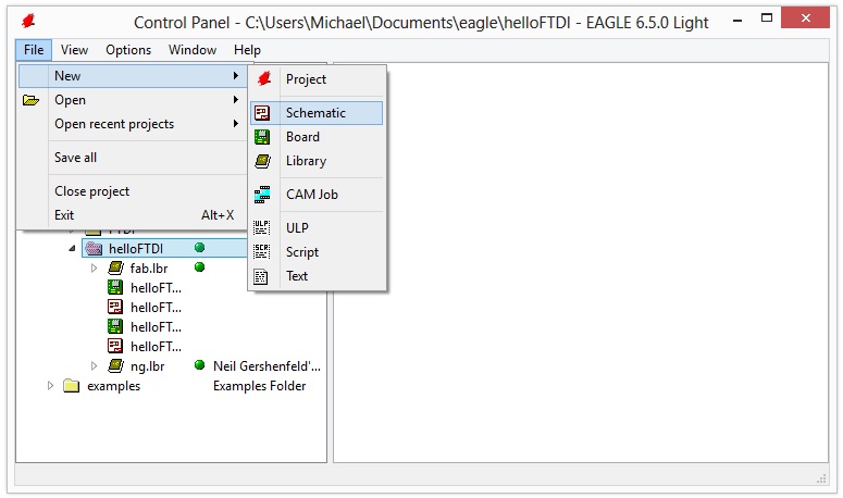
Schematic (.sch) : It is the representation of the circuit. Here we'll find the logical components.
Board (.brd) : Here we'll find electronic components and their connecting routes, distributed for obtain the file that will be used to mill the copper board.
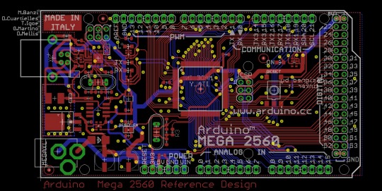
For a good tutorial in English on how to do a schematic, see: Eagle tutorial - schematic For a good tutorial in English on how to do a board, see: Eagle tutorial - board Tutorials in spanish: Schematic Board Step 6. Once that we already have some handling of Eagle (see tutorials quoted above), we opened the board that we downloaded in step 2. We have to note that the list of components that are being used is:
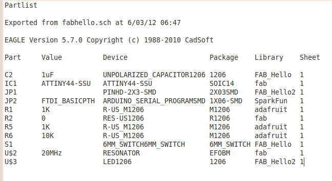
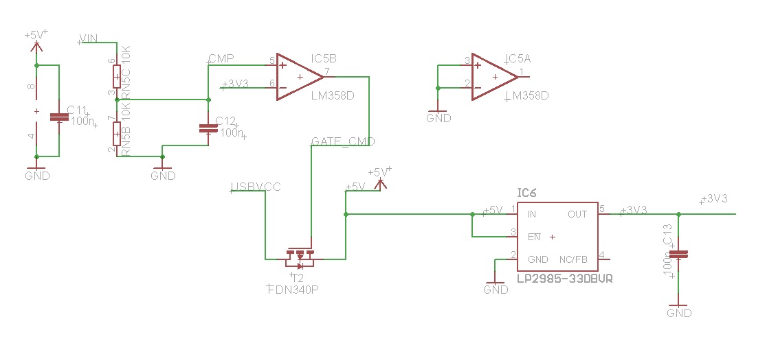
We will be guided of the image of board to create the schematic, taking advantage that the components can be found in the bookshops fab and ng.

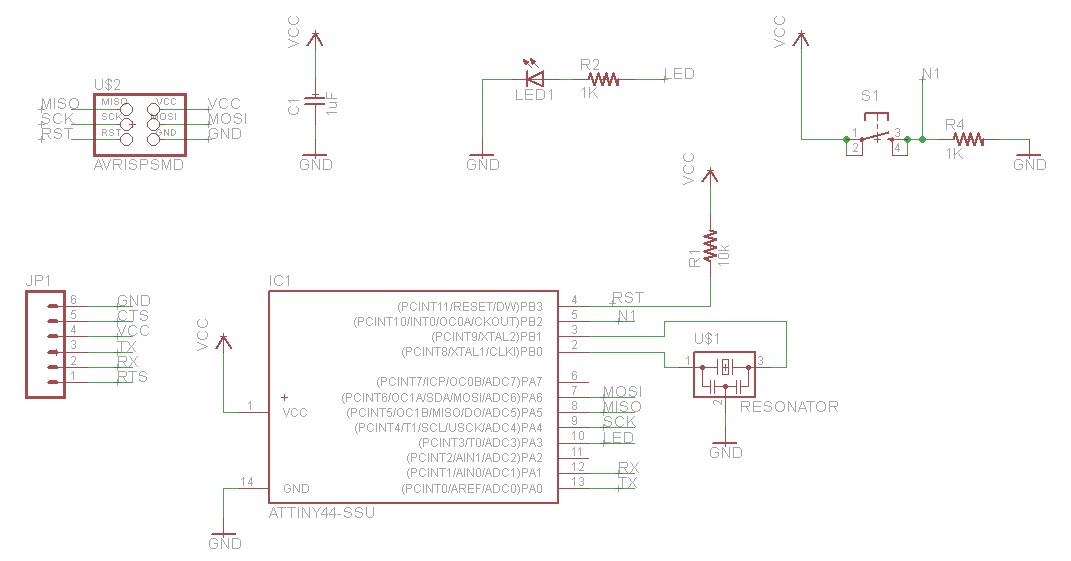
Note: Of all the components, only the led diode is the one with polarity, also be careful with the Attiny44 microcontroller and the orientation of his "pines". Step 7. We created a new schematic in Eagle, according to the list we are looking for each component in the libraries mentioned. We make the relevant connections and finally we add a green led, a resistor of 1k for the led, we add the button and a resistor of 1k for this same. We used pin 5 for the button and pin 10 for the led.
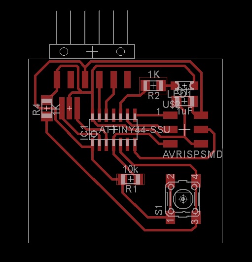
Step 8. We generate the file .brd This is the most difficult part, because we have to describe the connection paths the components by avoiding crosses and short circuit. For routes I used the default thickness. Also, normally you should not use routes with acute or right angles because they make the circuit become in antenna. Although this observation should be taken into account only when we use a larger resonator at 20 MHz.
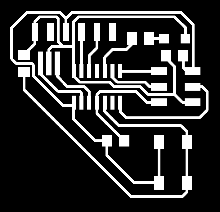
Archives: Board Schematic Step 9. We export the file board on monochrome option and a resolution of 500 dpi.
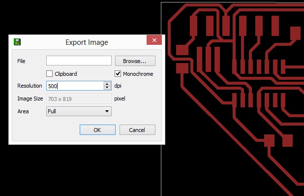
This is the result:
Step 10. We open the GUI of the Fab Modules. Step 11. We select the format and process that we will perform. In this case, PNG and Roland Modela MDX20. Step 12. We click in make_png_rml. Step 13. We load the file PNG of board. Step 14. We select the type of cutter that we will use (1/64) . Step 15. We regulate the parameters of milling. diameter: 0.4mm overlap: 0.5 offsets: 4 error: 1.1 pixels intensity: 0.5 z: -0.1 mm Step 16. We click in make_path, to generate the G-code that will be the file with the trajectories of headstock. Step 17. We cleaned up the copper board of impurities (isopropyl alcohol). Step 18. We put masking tape on the board in order to attach it in the iron of the Modela MDX20. Step 19. We calibrate the origin of the axes X and Y in the milling machine, considering the position of the copper board. Step 20. We calibrate the Z-axis, for an optimal milling of the board. Step 21. We give you click make.rml
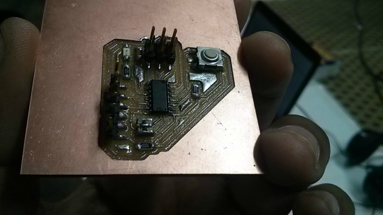
Step 22. We weld the devices on the board.
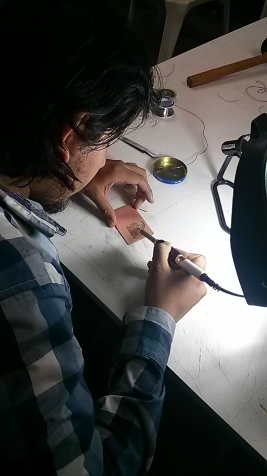
Step 23. Enjoy!