Computer Controlled Machining
The task this week was to build something big. For this purpose i decided to use the Shopbot CNC milling machine. Shopbot
The task this week was to build something big. For this purpose i decided to use the Shopbot CNC milling machine. Shopbot

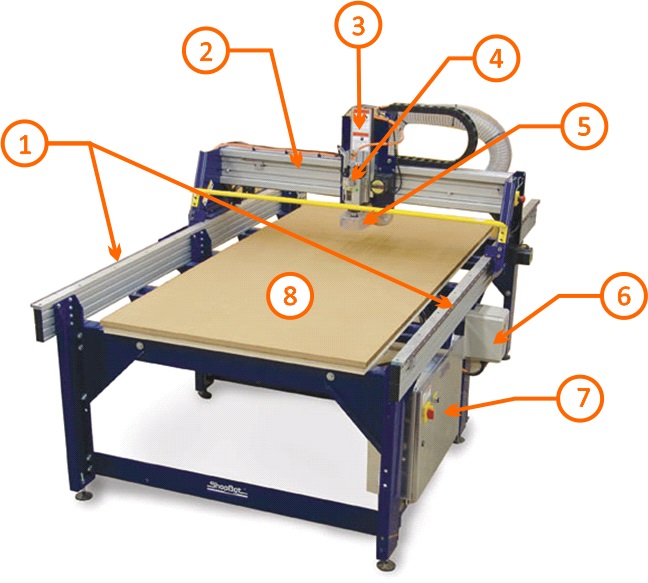
The Shopbot CNC milling machine is a machine of 3 axis of non-industrial use, it is used preferably for large parts. Works mainly with timbers and some types of plastics; also you can cut up to non-ferrous metals. This machine can also be used to create low-reliefs 3D using the appropriate cutting tools. The Shopbot allows us a working area of 2440 mm x 1200 mm. Parts of the Shopbot: 1. Rails of the X-axis (Bedplate) 2. Rail of Y-axis (Cart Y) 3. Rail of the Z-axis (Cart Z) 4. Headstock or Spindle 5. Skirt of the extractor of chip 6. Control box of the cabezal 7. General control box 8. Table (board sacrifice)
Exist some parameters to take into account during the milling, these are: FORWARD SPEED.- it is the travel speed of the tool along the axis XY. This parameter together with the cutting speed and the number of phyla of the strawberry define the size of the chip (chip load). LOWERING SPEED.- is the speed of penetration of the tool with the material along the Z axis Usually it is between a Terce and half of the forward speed. For milling 3D you can work a lowering speed next to the forward speed. CUTTING SPEED.- Is the speed of turn of the spindle of the headstock, therefore is the rotational speed of the cutting tool. DEPTH PASS: This parameter is directly related to the diameter of the strawberry. It is considered for normal work between 1 and 2 diameters of depth in passing. You can work up to 3 diameters of depth if it is required. The machine determines the number of passings according to the total depth. It is recommended that you use a value such that the last be thin between 1 and 2mm. STEP OR OVERLAP.- Is the portion of the diameter of the strawberry that performs the cutting when it produce a roughing. A biggest step requires fewer passings to cover one determined area, but a greater force on the part of the machine and viceversa. A prudent value is between 40% and 60 %. For milling processes of 3D in the finishing pass are recommended values lower than 10 %.when it produce a roughing. A biggest step requires fewer passings to cover one determined area, but a greater force on the part of the machine and vice versa. About my project, I wanted to build a model of generative manner. The first thing i thought was in use of Lindenmayer systems and develop a tree. Lindenmayer Systems They were introduced and developed in 1968 by the biologist and botanist theorist Hungarian Aristid Lindenmayer. These systems are a set of rules and symbols, used to modeling the development of the plants, also can be used to modeling the morphology of a series of agencies and fractals can be generated from the interaction of them. Some examples:

My inspiration was the work of the Japanese Hiro Tanaka.

The following is a code in processing that I modified to generate trees in 3D. I did this in order to take account of the final design and the corresponding measures.

import java.util.*;
Item axiom;
boolean clicked = false;
float scaleFactor;
float translateX;
float translateY;
void setup()
{
  size(600,600,P3D);
  sphereDetail(8);
  axiom = new Item();
  scaleFactor = 1;
}

void draw()
{
  background(#22bb66);
  lights();
  noStroke();
  fill(160,122,73);
  translate(translateX,translateY);
  scale(scaleFactor);
  translate(width/2, height, -height/2);
  rotateY(frameCount * 0.01);
  axiom.draw();
  if (frameCount < 6) {
    axiom.replace();
  }
}

void mouseClicked()
{
  if (mouseButton == LEFT) {
    axiom.replace();
  }
  else {
    axiom = new Item();
  }
}

void mouseWheel(MouseEvent e)
{
  translateX = translateX-e.getAmount()*(mouseX)/100;
  translateY = translateY-e.getAmount()*(mouseY)/100;
  scaleFactor += e.getAmount() / 100;
}
class Node
{
  PMatrix3D transform;
  int geometry;
  Vector children;
  Node()
  {
    transform = new PMatrix3D();
    geometry = 0;
    children = new Vector();
  }
  void draw()
  {
    if (geometry == 0) {
      applyMatrix(transform);
    }
    else {
      pushMatrix();
      applyMatrix(transform);
      switch (geometry) {
        case 1:
        box(2,2,2);
        break;
        case 2:
        sphere(1);
        break;
      }
      popMatrix();
    }
    for (int i = 0; i < children.size(); i++) {
      pushMatrix();
      Node n = (Node) children.get(i);
      n.draw();
      popMatrix();
    }
  }
}
final int X = 0, A = 1, B = 2, C = 3;

class Item extends Node
{
  int type;
  Item()
  { type = A; }
  Item(int t)
  { type = t; }
  void replace()
  {
    for (int i = 0; i < children.size(); i++) {
      Item n = (Item) children.get(i);
      n.replace();
    }
    applyRules();
  }
  void applyRules()
  {
    switch (type) {
      case A:
        // A (void) -> B (a vertical shape)
        type = B;
        geometry = 1;
        transform.scale(10,75,10);
        transform.translate(0,-1,0);
        break;
      case B:
        // B (a vertical shape) -> C (+A) (-A)
        type = C;
        geometry = 2;
        float r = random(0,TWO_PI);
        // the "X" is the + transform
        Item c1 = new Item(X);
        children.add(c1);
        c1.transform.translate(0,-150,0);
        c1.transform.rotateY(PI/2);
        c1.transform.rotateZ(PI/4);
        c1.transform.scale(0.7);
        c1.children.add(new Item());
        // the "X" is the - transform
        Item c2 = new Item(X);
        children.add(c2);
        c2.transform.translate(0,-150,0);
        c2.transform.rotateY(-PI/2);
        c2.transform.rotateZ(PI/4);
        c2.transform.scale(0.7);
        c2.children.add(new Item());

        Item c3 = new Item(X);
        children.add(c3);
        c3.transform.translate(0,-150,0);
        c3.transform.rotateY(TWO_PI);
        c3.transform.rotateZ(PI/4);
        c3.transform.scale(0.7);
        c3.children.add(new Item());


        Item c4 = new Item(X);
        children.add(c4);
        c4.transform.translate(0,-150,0);
        c4.transform.rotateY(PI);
        c4.transform.rotateZ(PI/4);
        c4.transform.scale(0.7);
        c4.children.add(new Item());
        break;
    }
  }
}
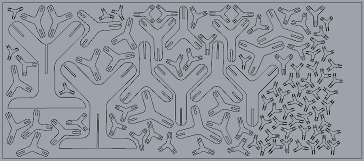
Modeling in Solidworks The modeling was not complicated, since it was rescale the piece from another base piece. The greatest difficulty that I had was to define the number of iterations to prevent the branches intersect, for this served the program processing. Then, I rescale all the pieces to the 70% (this for each iteration), taking into account that she was going to work with a wood of 15 mm thick. At the end, the design was required 98 parts.
Downloading link for my archives: Archives Manufacturing For their manufacture I had to export the parts that I did in Solidworks in DXF format and edit them in Rhinoceros. As my design was using a wood 15mm of thickness, I had to adapt it to the woods available.
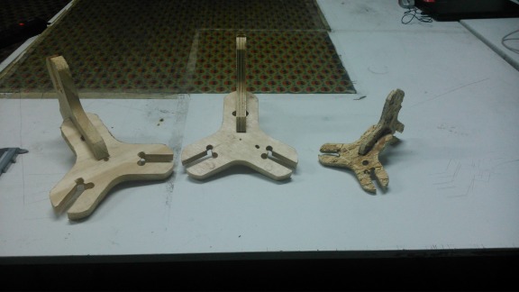
The first thing I did was test with plywood phenolic of 18.5 mm thick, then for the tolerance test I had to make the cuts taking 18.9 in the design. I had to discard this possibility because they didn't have enough material for the 98 pieces, because the work was going out more than one wooden board. The following was to prove in OSB with 11.6 of thickness, then for the tolerance test I had to make cuts taking 12.6 in the design. To test I send some pieces for cutting and the result was not expected because the pieces broke easily. Finally, I used MDF of 9.3 mm thick, this presented a result quite clean. In the design I had to consider the cuts for pressfit with 10.2 of tolerance.
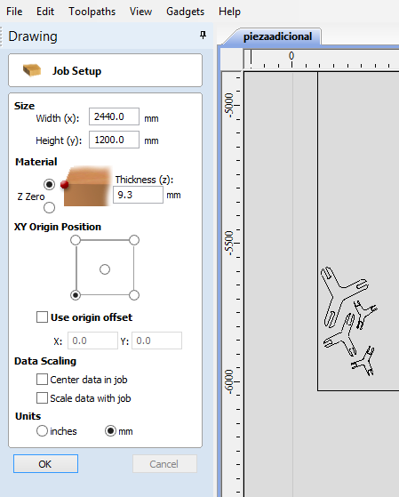
Manufacturing process: 1. Open PartWorks that is the software of the Shopbot. 2. Load the file DXF 3. Appears the tab Job Setup and here we do the following: Select the work area that is of 2440 mm by 1200 mm. Deselect the tab "Use origin offset" We select the units (mm) Click on OK
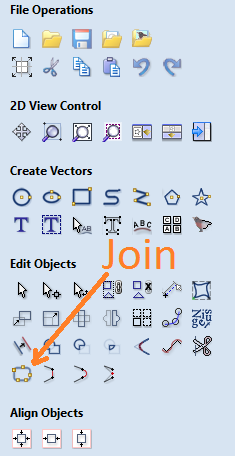
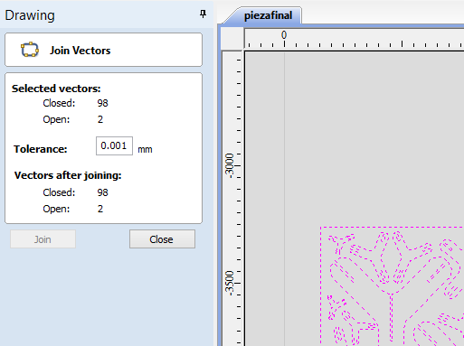
4. We select everything and we click "Join vectors", so that the curves are closed. If necessary increase the tolerance to terminate to close the curves.
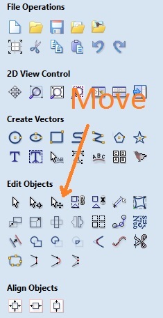
5. We select everything and we click "Move, scale, rotate selection", to move the vectors to the origin of the board.
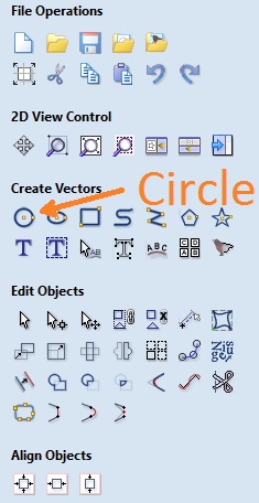
6. Then we click to "draw circle" to draw the circumferences that they will serve as a reference for place the screws. As our strawberry is 6.35 mm, we have to do circumferences of at least 6.5 mm. Observation: It is important that in the design we have considered the size of the strawberry, because we cannot make right angles or treble interiors, in this case, we must make circumferences of larger diameter to 6.35 mm in these corners.
7. We click the tab "toolpaths" and it will appear several options.
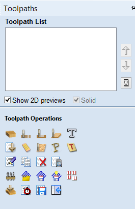
8. In that menu we select the operation "create drilling toolpath" and we will access to another menu. 9. In this new menu we select all the circumferences that we did with the shift key and we click "Calculate".
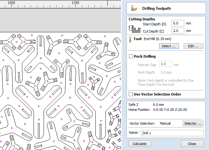
10. A program will take us to a 3D view and we click the option "preview visible toolpaths", we will see a simulation of what it will do the machine. Then click on Close.
11. We select the new flunge of the model and now we go to re-select the tab "toolpaths" and then the operation "create profile toolpath" and it is going to appear the following menu:
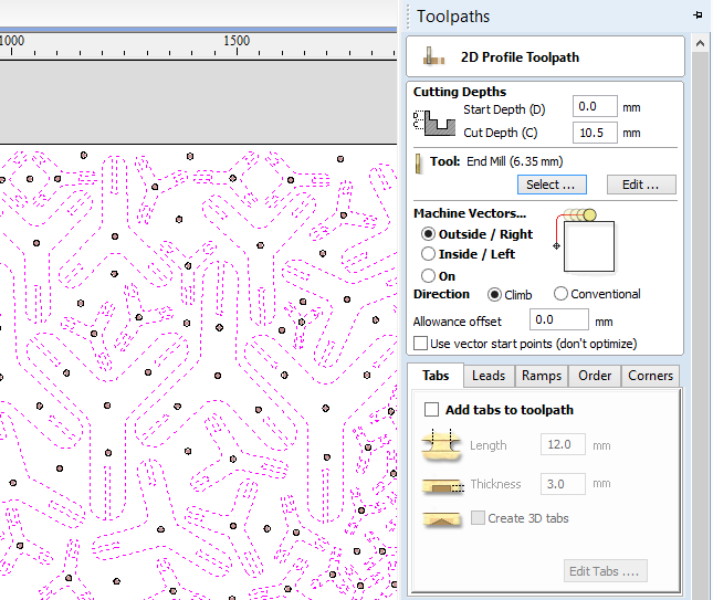
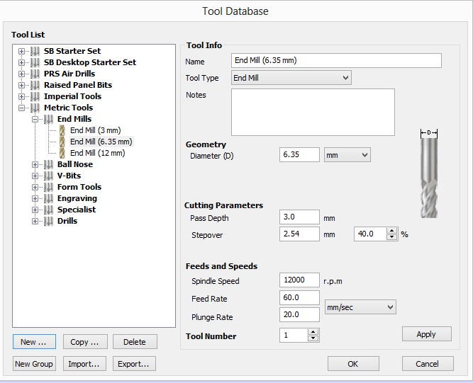
Here we chose the depth of the cuts, the type of cuts (external or internal), the tool to use, and so forth. Start Depth: depth of start. Cut Depth: depth of cut. Tool: here you will select the tool, type, size. Machine Vectors: If you want to cut on the outside, Inside if you want to cut inside. Directions: If you want to follow a clockwise , Conventional if you want to follow a counterclockwise. Allowance offset: allowed area between cuts. 12. Select the parameters according to the material, already described in the previous step. It is essential if you want to make assemblages, see the cuts to the union in the assemblage have the same selection in machine vectors. We have the following options: Pass Depth: determines the depth of the tool on each pass. Stepover: determines how much more the tool superimposed on each pass, during the rasterised. Spindle speed: determines the speed of turn, this is based on the material, diameter, the rate of progress of the tool and the rate of immersion. Feed Rate: determines the rate of progress. Plunge rate: determines the rate of immersion of the tool.
13. We selected all the curves of the parts to be cut, to our pieces we choose the cut for the outside. We click on "calculate". 14. The program is going to take us to a 3D view and we click in the option "preview visible toolpaths", we will see a simulation of what it will do the machine. Then click on Close.
15. Store the files with extension sbp. 16. Open the Shopbot program, and we pressed the button azul. 17. Press k to use the keyboard and moving the tool (previously the material must be bolted). Use the keyboard arrows to control the position in the X and Y, position for use Z Pg Up and Pg Dn.

18. To calibrate the Z position, we click on Cuts we chose C2 - Zero Z axis w/ ZZero Plate and use the metal plate for calibration. The strawberry lowered twice and tcara the metal plate to calibrate the height. 19. To calibrate the posixion XY, we click on Cuts and chose Zero - XY axis. 20. We load the file drill and we click to start. To start the process of milling we press the green button.
21. To screw the parts using the brands like guide. 22. We load the profile of court and we click to start. To start the cutting process we press the green button.
23. We move the headstock of the Shopbot to unscrew the pieces. 24. Enjoy!
Downloading link for my archive: Archive