This week’s task was to try different 2D and 3D design softwares.
Sculptris
The first software I used was Sculptris, this is a free software specifically designed to model characters sculping them.
The interface is quite friendly, we part from an sphere that we will be modeling until we obtain the desired result.
To the left, we have the following menu:
Crease is used to mark the material as when engraving.
Draw is used to add material. This option can also allow you to remove material when pressing "alt" and soften the surface by pressing "shift".
Flatten is used to flatten the surface.
Inflate is used to inflate the surface.
Pinch is used to pinch the surface from a point.
Smooth is used to soften the surface.
My first project with this software was to créate a face by using the program that allows me to work with symetry, which makes easy the modeling.
To model a face it is necessary to have in mind certain proportions, that all faces have and the most important thing (to me at least), is to make the face with particular imperfections, because I believe that is what makes every face unique.
In order to make the lips, we used Crease as it allows to correctly define the outline.
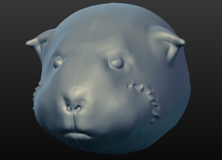
The next project with this software was to make the head of the guinnea pig because I want to mold it in resin. This is for my final project.
And this was the result:
Downloading link for the program:
Sculptris
Downloading link for my archives:
Archives
Rhinoceros
The next software I used was Rhinoceros, which is a licensed software, it is designed to model products, furniture, structures and complex geometric systems via Grasshopper.
Rhinoceros is based on NURBS tecnology (non-uniform rational B-spline), which is a mathematical model based on Pierre Bézier´s theory to generate curves and surfaces. This makes it very popular in graph computation.
Grasshopper is a Rhinoceros plug in that allows us to create models by using graph programming (nodes via). It is oriented towards generative designs.
For the next project I thought making a compact fluorescent lightbulb as a complex surface generated with Grasshopper. The most dificult part of the lightbulb was to make the base nut. I used a reference image to this and draw half of the outline, for the nut I used curves and then the revolution tool for two rails. The rest of the Project was made using the revolution tool.
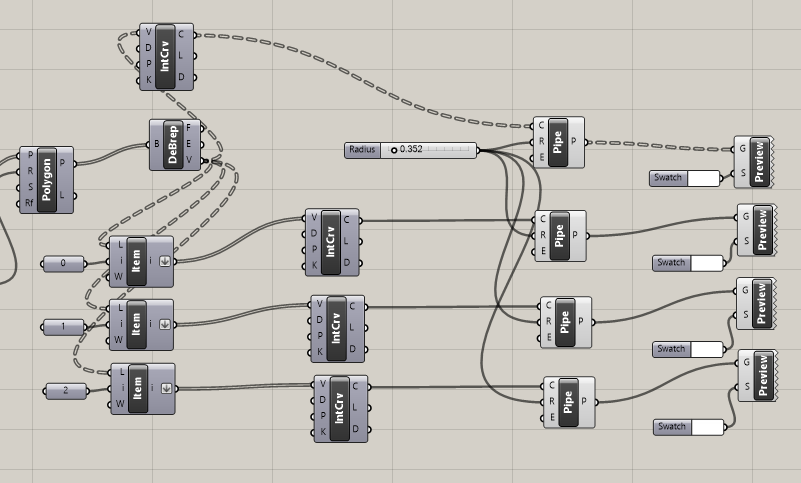
The fluorescent light was made creating three triquetras with curves and then using the pipe module of Grasshopper. Finally, using planes throughout the triquetras, we graphed a circunference ortogonal to the curves in each plane and by using the pipe tool again we obtained the following result.
SolidWorks
Having already a software to sculpt and one to create 2D and 3D designs, the next thing I did was look for a tool to model and simulate mechanisms.
Solidworks it is a specialized software in mechanisms, and also requires a license for use, allowing us to make parametric designs more easily using geometric relationships, such as symmetry, coincidence, etc.
The other unique feature is that we can do the parts of the mechanism separately and then assemble them.
The first thing to do is choose the outline in which we will model the piece and create a rough sketch.
We have to model in 2D the sections using the tools of line and polygosn, to fasten the parts we must use the intelligent dimension tool, with which we give the dimensions to each section of the piece.
To obtain the part in 3D, we use the tools from the operations menu, extruding when necessary and creating planes to model the other parts.
For this project I decided to validate my design of the mechanism of Theo Jansen, which I'll use in my final project and to simulate it, I choose the option "study of movement".
Downloading link for the program:
SolidWorks
Downloading link for my archives:
Archives
Meshlab
The next step was to use a software that will let me edit a created model, improving its texture or correcting mesh errors.
For this purpose I used Meshlab, which is a free software and works with many formats.
The interesting thing about Meshlab is that there are different types of filters to work with. A strong motivation was to experiment with Voronoi designs.
Voronoi is a method of interpolation based on the Euclidean distance, this construction allows us to tessellate the plane (R^2), but a generalization of this technique enables us to work in 3 dimensions or R^3.
To use this technique with Meshlab, we must have a meshing of design, then we use the Poison filter to obtain points in the meshing.
The next step is to use Voronoi Vertex tool for coloring mesh in all the points that I obtained with Poison filter and select the option "BackDistance".
Now we are going to "Select Faces by Vertex Quality" to convert the model in two colors. Finally we invest the selection and removed the unwanted material erasing what is selected.
For best results, you can apply filters as "Laplacian Smooth" and then "Uniform Mesh Resampling". And to smooth out this new 3D model we used "Taubin Smooth".
Below you can see the result of applying the technique to a 3D model.
Downloading link for the program:
Meshlab
Downloading link for my archives:
Archives
123D Make
From the family of the 123D Autodesk software, this tool helps us to obtain different types of models from a file in 3D. The reason I chose it because I wanted to experiment with the technique Waffle. 123D Make comes with the option "Interlocked Slices".
Sometimes it is necessary to adjust the thickness values of each section or regulate dimensions to avoid errors.
The following is an example of what can be done from a rhinoceros model.
Downloading link for the program:
123D Make
Downloading link for my archives:
Archives
Meshmixer
Also belonging to Autodesk, this tool serves to sculpt like Sculptris, but has more advantages when making edits. Specialized to merge surfaces and make corrections in the mesh automatically.
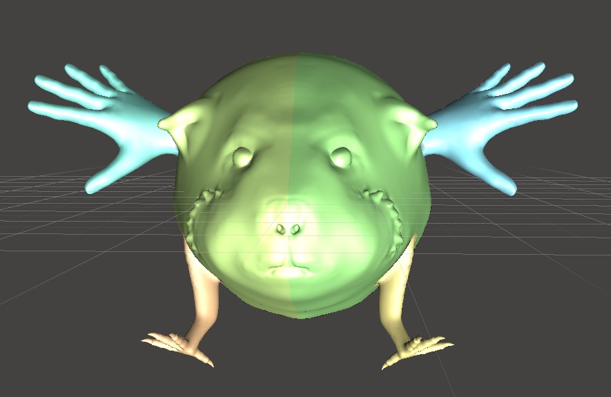
This tool is very interesting if we want to edit surfaces by mesh.
The following is an example where I reuse the head of the guinea pig for mixing with other surfaces.
Downloading link for the program:
Meshmixer
Downloading link for my archives:
Archives
Processing
Finally, after trying a number of softwares I decided to create my own program for generative surfaces by triangulation. For this I used Processing.
Processing is a programming language and development environment based in Java, is most common for visual applications and interactive systems.
The libraries that I used for the filter designs are Toxiclibs, for GUI ControlP5 and Peasycam for visualization.
The program I did generate OBJ files, we can control the number of divisions and the smoothness of the surface.
Each time you want to modify the parameters to make the necessary changes press "redibujar".
The following is a capture of the GUI and the code for this app.
Final Project Actualization
For my final project, I design an skeleton using a modification in Theo Jansen's mechanism.
I decided to use a modification of the mechanism because the guinea pig has a different way of walking the animals which are usually using this mechanism in kinetic sculptures.
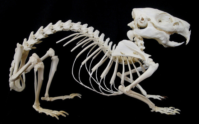
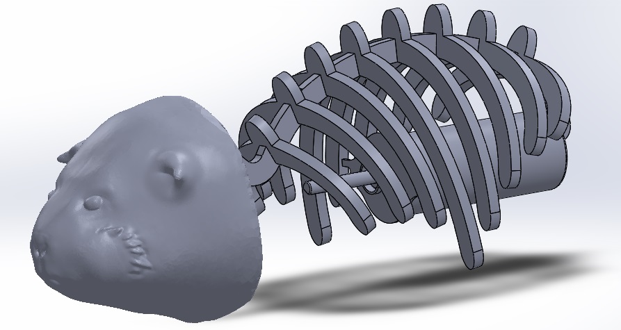
I tried to guide me of the original skeleton of a guinea pig:
Then using the head, I modeled the ribs and trunk for the laser cutter. I will use acrylic with 5 mm thick.
About the legs, my main reference is Theo Jansen's mechanism. But, there is many walking mechanism's like chebyshev walking mechanism or Klann mechanism.
An article that was an inspiration for me, is next:
A new type of mechanical walking machine
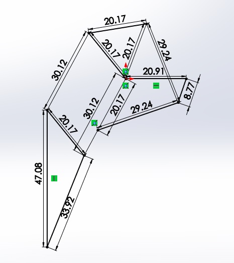
My first idea was modified the parameters in Theo's mechanism, looking for a similar movement of a guinea pig.
I chose this parameters for the links:
The next is a simulation of the mechanism modified:
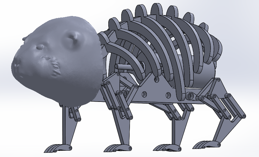
The complete skeleton of the model
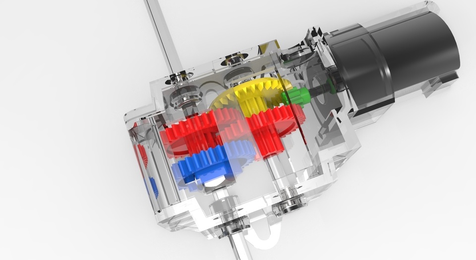
For the transmission of motion I will use gears and a toothed belt. Internally I'm planning to use a mechanism like Tamiya Gearbox for one DC motor. But I build this gears using the Modela MDX20.
Technical details:
The nodes have 3 mm of diameter.
The nodes for motion transmission have 6.5 mm of diameter.
The length of model is 274.68 mm.
The head height is 98.56 mm.
The legs height is 80 mm.
Downloading link for my archives:
Archives