
Networking and Communications (Week 13)
The Assignment for this week was to design and build an wired &/or wireless network connecting atleast two nodes.
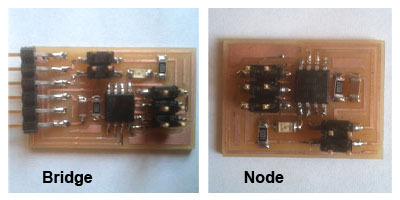
I began by milling the bridge and node boards available on instructions page put up by Neil on Fab Academy website (link). Once done, I stuffed the board with components. This was quick as the number of components was less. However, I must confess, I soldered the LED incorrectly and had to re-do it. Error was in the orientation of component - the end with a line is the cathode and connects with ground on the board (note to self :) ).
I connected the node with bridge using ribbon wire + connectors and plugged in AVRISP2 + FTDI Cables.
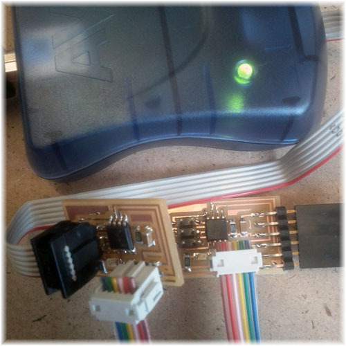
Green light on AVRISP2 indicated that the boards are ready to program. I downloaded hello.bus.45.c from the fabacademy site, which had to be edited for bridge and each node.
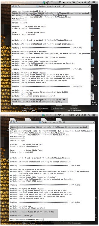
I opened C file and edited the code to reflect node id as ‘0’ for bridge. Next up, I ran the following command “sudo make -f hello.bus.45.make program-avrisp2” on terminal which gave me a fuse error. On affirmative reply, the programming was successful.
To program the node, I changed the node ID to ‘1’ in C File and re ran “sudo make -f hello.bus.45.make program-avrisp2” on terminal.
I visualised my circuit on Arduino IDE’s Serial Monitor. First set the baud rate to 9600 and then type the node ID near the send button and hit send. Here’s the video ! Please watch the video on mute or low volume as there is a lot of sound disturbance from the milling machine.
(UPDATE)
I eventually figured out that I was connecting the two nodes and the board incorrectly. On running a google search, I came across Anu’s fabacademy documentation which helped me solve this puzzle.
Incorrect connections. The AVRISP2 is supposed to be connected to the node and not the bridge.
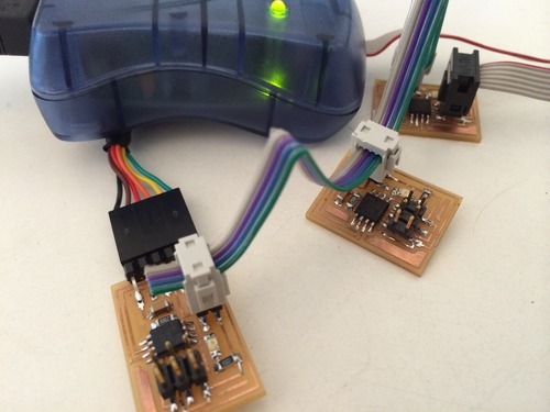
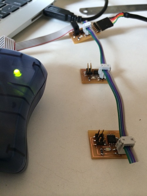
Correct connections. The AVRISP2 is supposed to be connected to the node and not the bridge board.
I also re-soldered the components on the 2nd node and rechecked alignment.
After this little excercise, it was easy to code and visualise the circuit.
The new video link.