Electronics Production
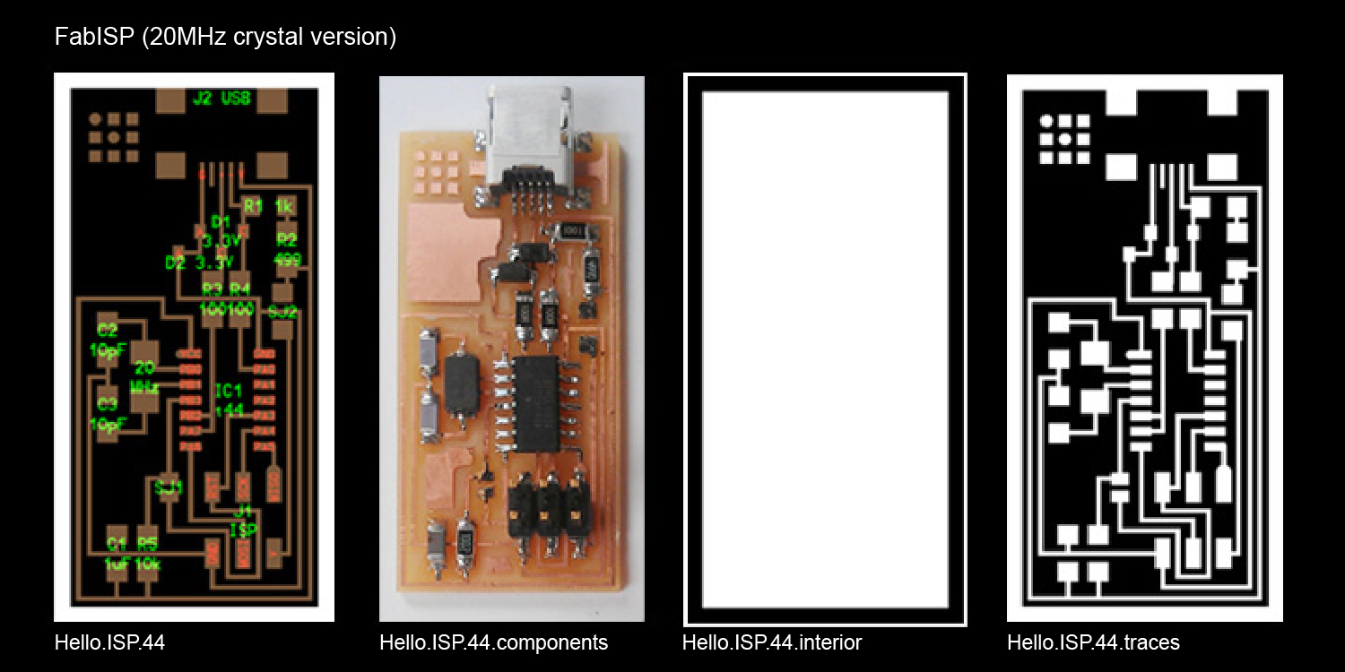
The FabISP is an in-system programmer for AVR microcontrollers, designed for production within a FabLab. That is, it allows you to program the microcontrollers on other boards you make, using nothing but a USB cable and 6-pin IDC to 6-pin IDC cable. It's based on the USBtiny and V-USB firmwares, which allow the ATtiny44 to perform USB communication in software. Programming can be done through avrdude. The schematic (PDF) is super simple: USB connector, ATtiny44, and 6-pin ISP header, with assorted passive components. I started with the Eagle files for the USBtinyISP, although there's almost nothing left of it. Most of the parts for the FabISP are in the FabLab inventory. Exceptions include the Mini-B USB connector (SparkFun, Digi-Key), 12 MHz crystal (Digi-Key), and 18 pF capacitors for the crystal (Digi-Key).
Fab Academy Barcelona Class No.5
Assignament: Electronics Production "The FabISP"
By Robert Garita
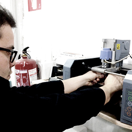
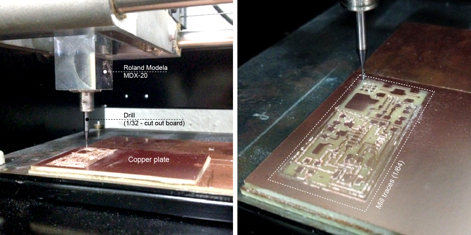
Machine: Roland Modela MDX-20 milling machine
Software: Modela
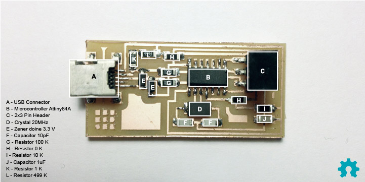
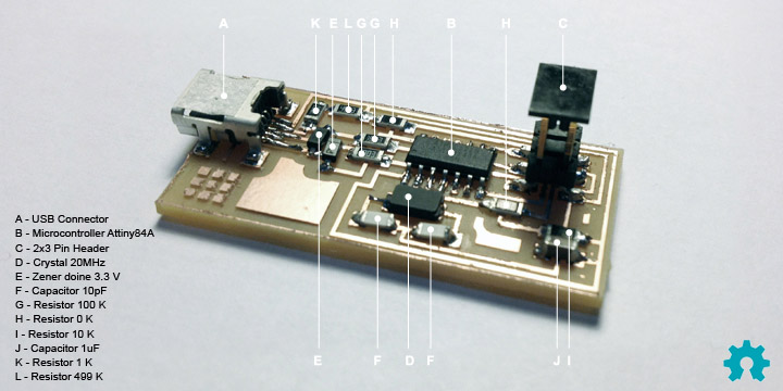
Materials: Copper plate, Microcontroller ATTINY44A, Crystal 20MHz,USB connector,Ribbon connector, Zener diode, Jumper,Programmer AVR
Assignment:
Make the FabISP in-circuit programmer.
For this week we have to fabricated the first PCB board with the Roland Modela. I decided to use the design of David A. Mellis. This board use a small microcontroller, the ATinny44 and it can be programmed with the Arduino software.
Im going to follow 7 simple steps for the production of my FabISP in-circuit programmer:
1) Download the hello.ISP.44 png’s for the trace and end.
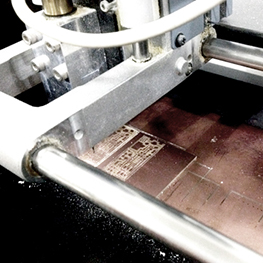
2) Milling the trace:
2.1) Clean the surface of the copper with alcohol and use double-sided tape to attach it to the existing base on the iModela milling machine.
2.2) Reset the Modela coordinates, insert the 1/64 bit and using Fab Modules, move the origin to the desired corner. Lower the bit until it just about touches the copper surface.
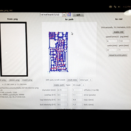
2.3) Using Fab Modules, load the PNG, turn it into an RML and make the .path
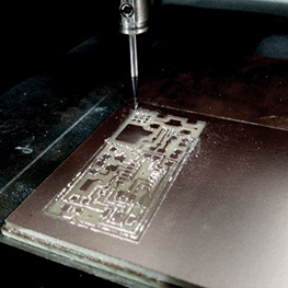
2.4) Send to mill the trace.
3) Cutting the board: repeat the same steps as the milling but using a 1/32 bit (with appropriate settings) and loading the outline PNG.
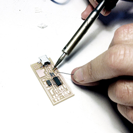
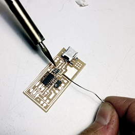
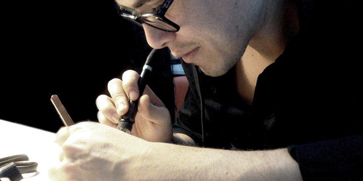
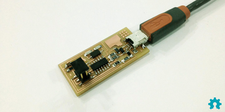
4) Follow the board guide and solder the necessary pieces (capacitors, resistors, chip, crystal, mini USB header).
5) Install the software for AVR programming (Avrdude, GCC).
6) Power the FabISP board with a separate programmer plugged into the 6-pin header and program the FabISP.
7) Remove the 0 ohm resistor and solder bridge from the board.
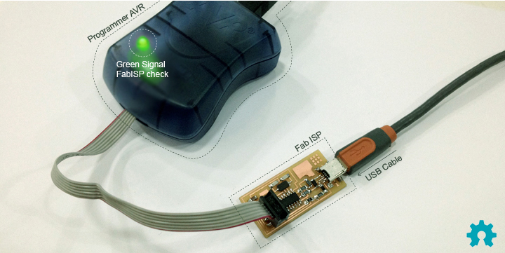
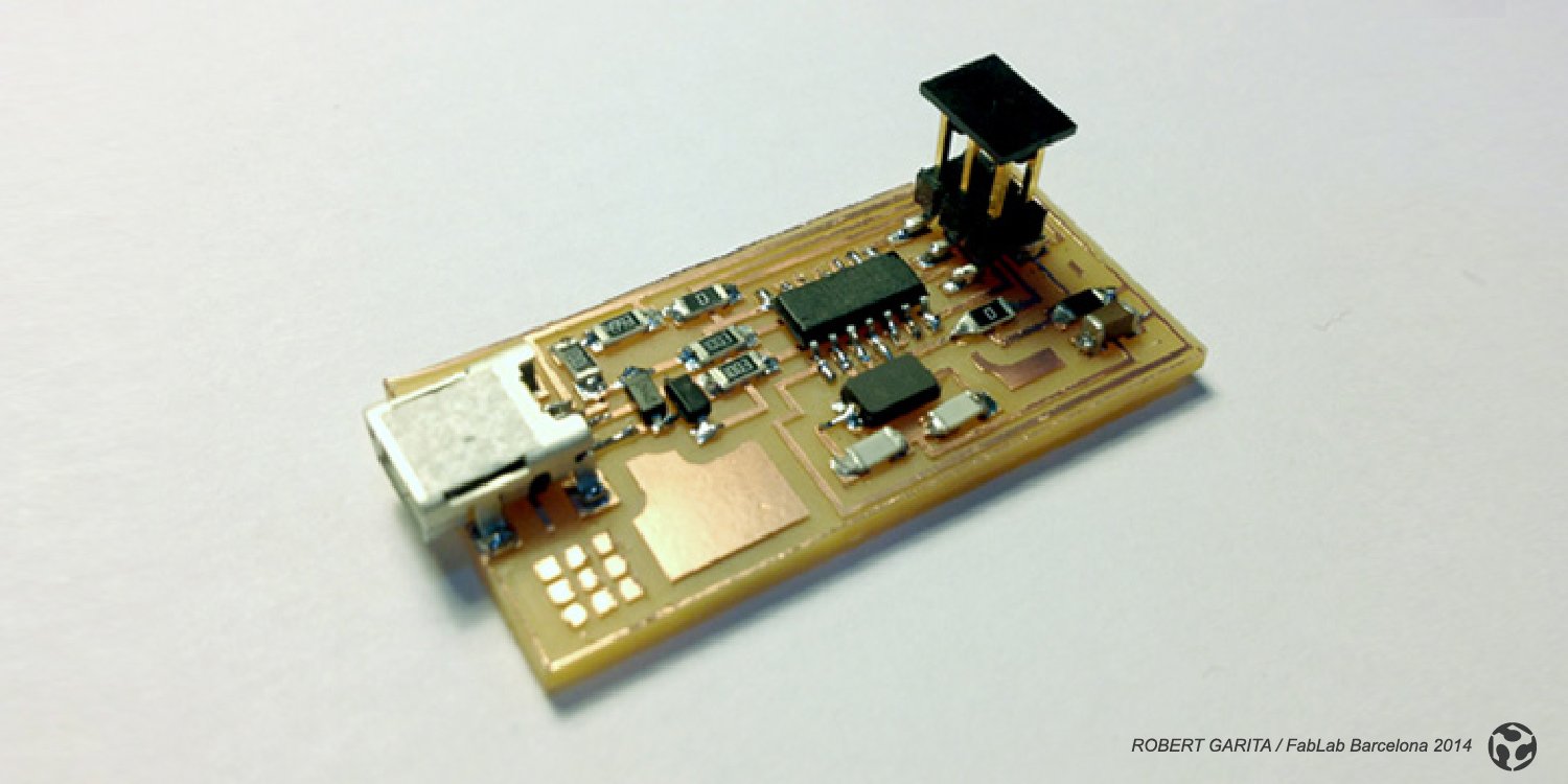
And if you are lucky you will have a succefull, built and programmed board and recognized by your Computer when you plug it into the USB port.