 |
|
 |
|
For this assignment I had to modify a eagle circuit (echo hello world board) in order to add two components :a button and a LED with current-limiting resistor, after that make the board through milling process and finally solder the components The process begins using Eagle softwar to make the schematic. You have to download the fab-library and copy it into documents-eagle floder in order to be able to use it.
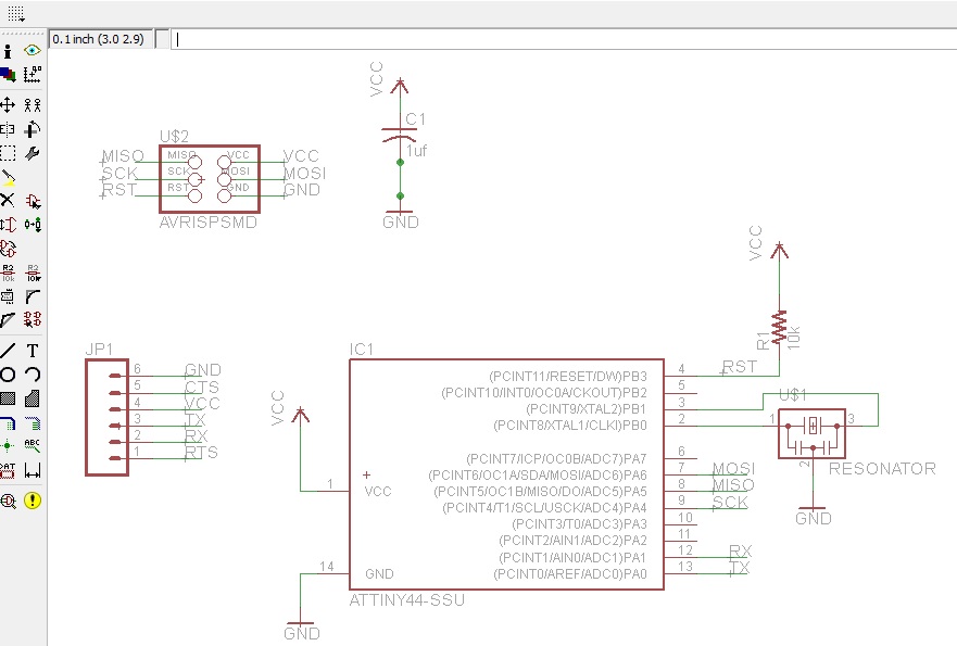 Photo 1:Original eagle schematic After add the button and LED with current limiting resistor: 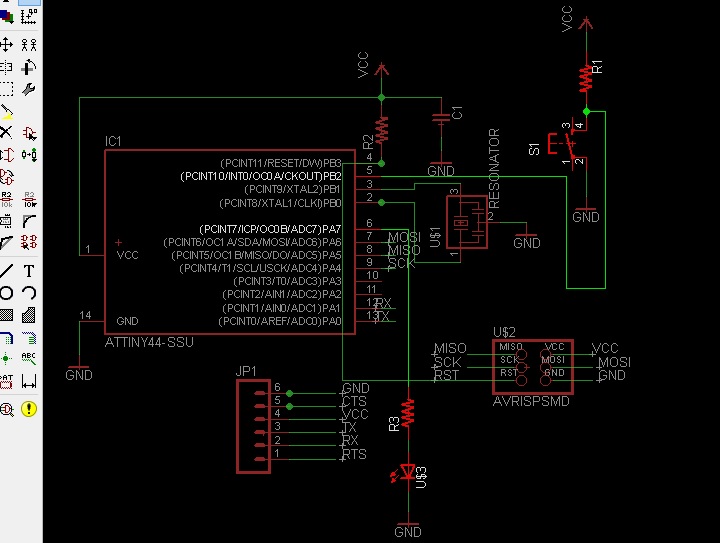 Photo 2: my version, the added componets are highlighted The next step is to make the routing 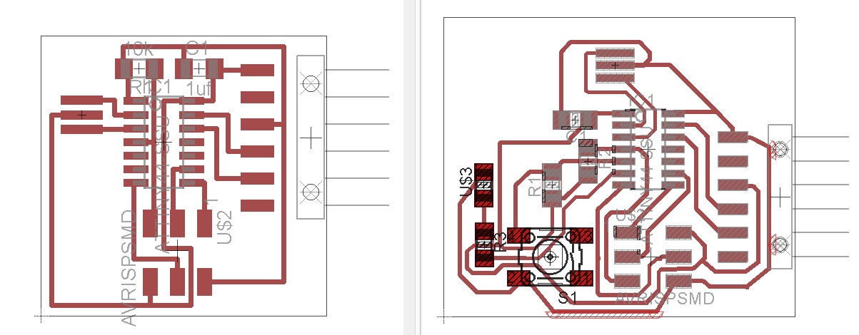
Photo 3: The original and the modified version Once you finish your design you can start the fabrication process, for that you have to export the image from eagle in monochrome but be carefull because the following could occur: . 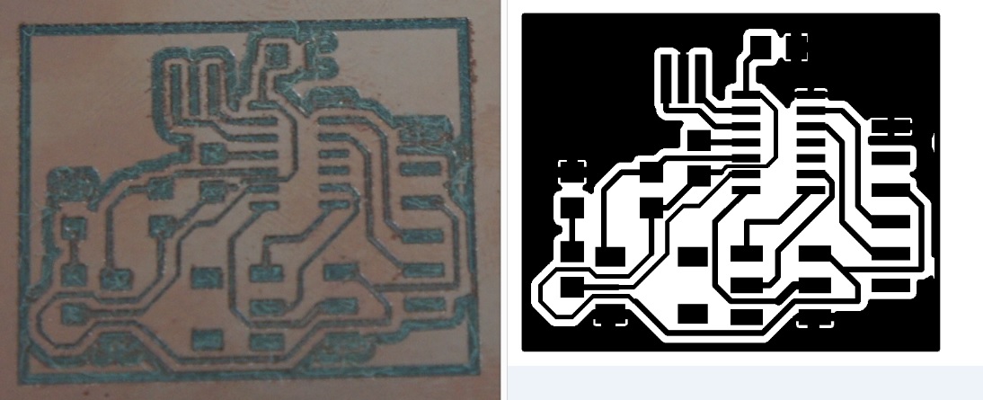
Photo 4:Milling the wrong part What happened?... the machine remove all what is on black color, So if you get the image like photo 4 (right) you must to invert the color, in my case I used Gimp to do that.
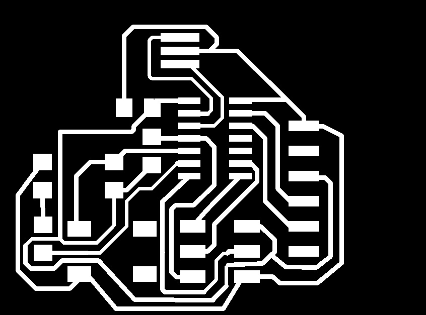
Photo 5:The right colors to fabricate OK, once you have the right image letf's open fab modules on ubuntu by typing "sudo bush-password-fab", select the PNG file type and Roland modela rml 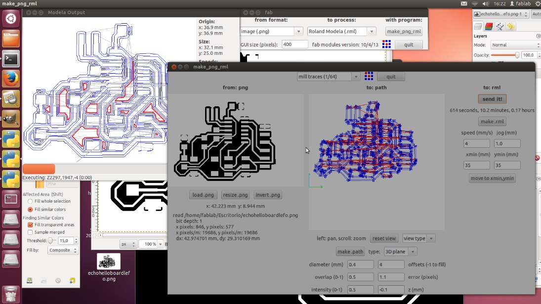
Photo 6:Fab modules interface Then fix well the board on the machine platform and calibrate the "z" axis, start milling 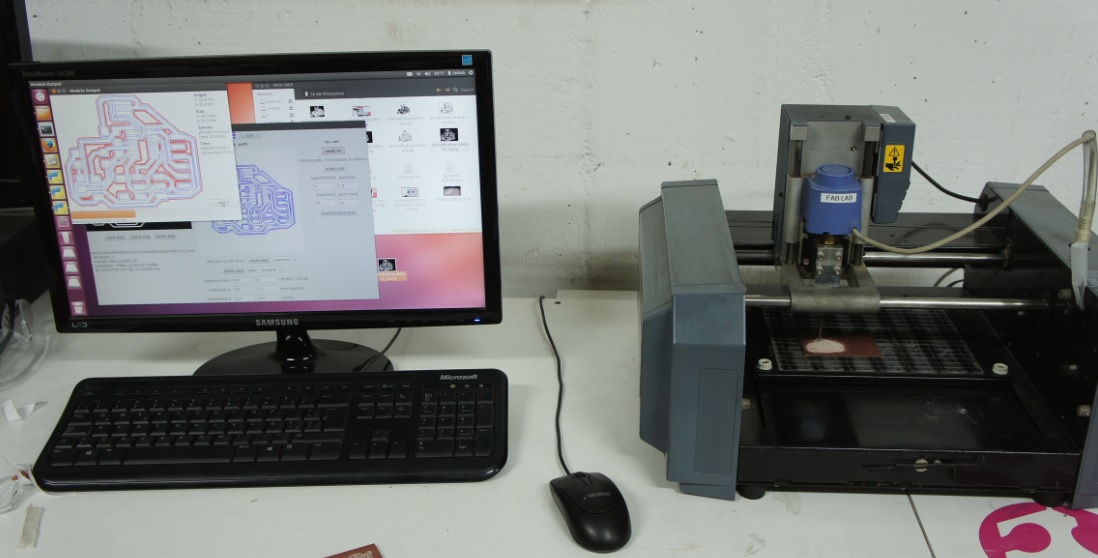
Photo 7:Milling ...Then the soldering process... 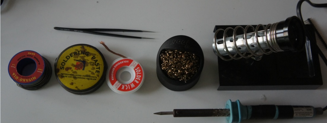
Photo 8:Welding tools List os componets 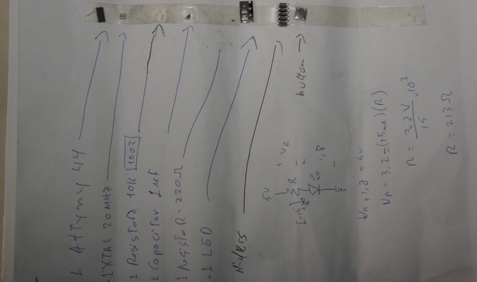
Photo 9:List of components 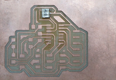
Photo 10:Resonator soldered After solder all components: 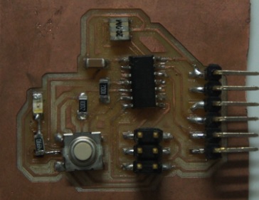
Photo 11:Final product Files: Mediafire https://www.mediafire.com/folder/0h141nl9bpoup/elecDesignGithub https://github.com/lefolindo/ElectronicsDesign |