 |
|
 |
|
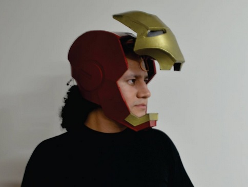
This time the challenge is to build "something BIG" using the shopbot machine. I decided to make a Big mechanical iris, the process begins designing it with Autodesk inventor
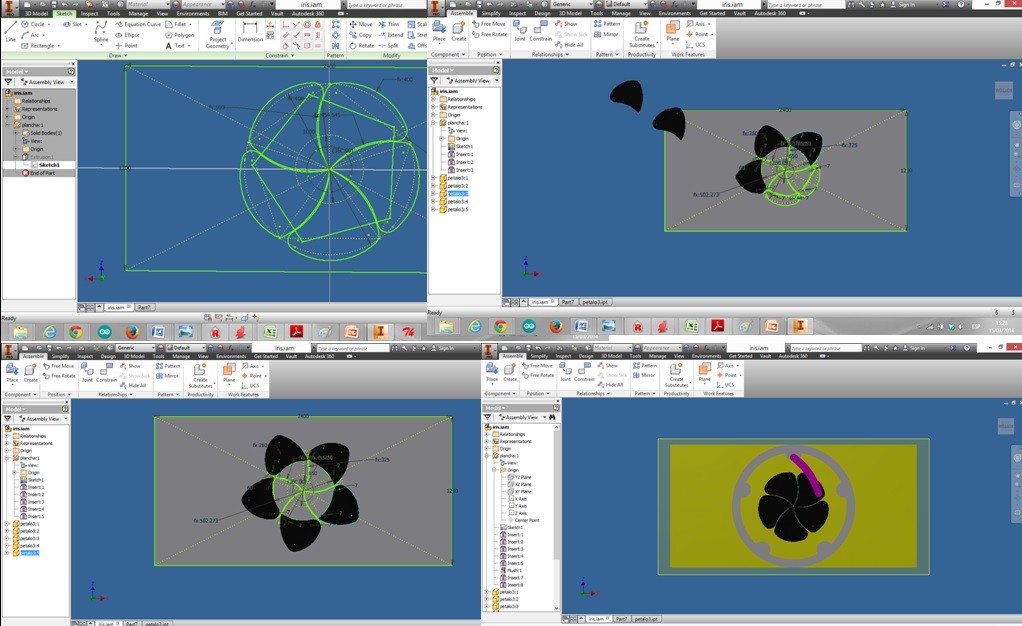 Photo 1:Disigning on invntor
 Photo 2: 3D model completed Here you can see a video of the simalation: The next step is to export the faces into DXF format in order to use PartWorks 3.0 which is the native software of the shopbot machine. It is a good practise gather and sort all parts before using Partworks, I used Rhinoceros. 
Photo 3: Distribution of the parts on rhinoceros Once you finish your design and distribution of the parts you can open the dxf file with PartWorks: 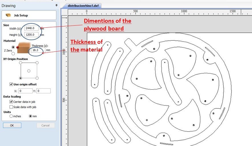
Photo 4:PartWorks I used playwood of 18.3 thickness and 2440x1200 mm
OK, then the process consist in generate " toolpath operations" basically 3 types: Profile, Pocket and Drilling 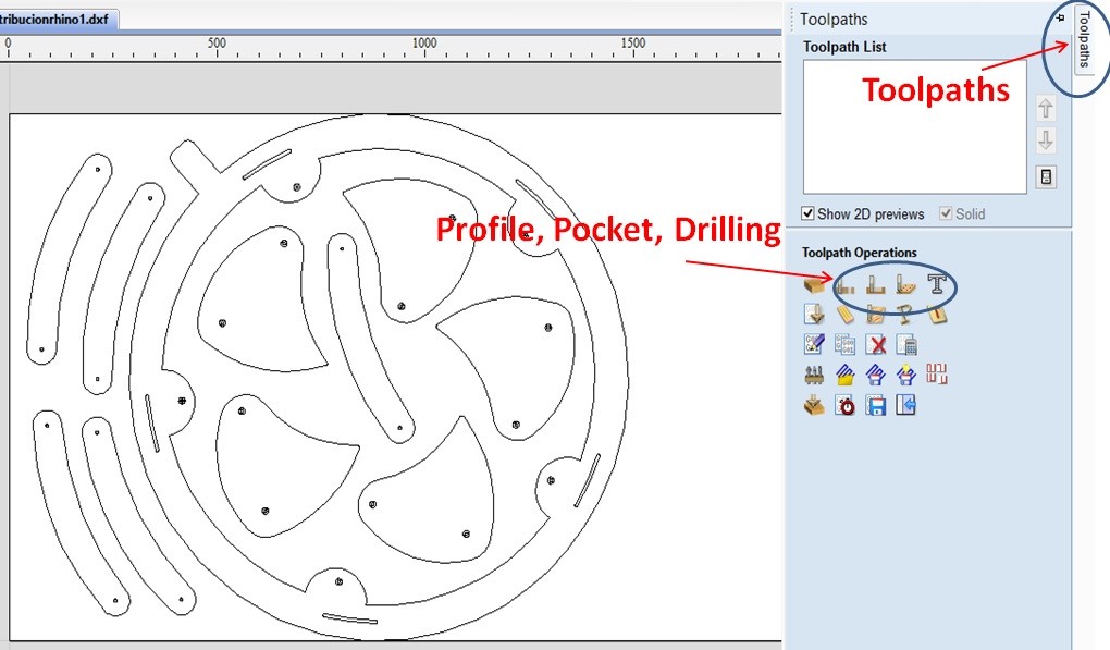
Photo 5:Toolpath operations First we have to make a drilling toolpath in order to mark the positions of the screws to fix the playwood to the work plataform, look at the following picture, I've put two screws for each piece using the circle vector, it have to be the same diameter of the milling tool you are using. You have to put some aditional screws to fix the parts of the board between pieces. The click on "calculate"and the software generates a simulation of the machining. 
Photo 6:Making a Drilling toolpath
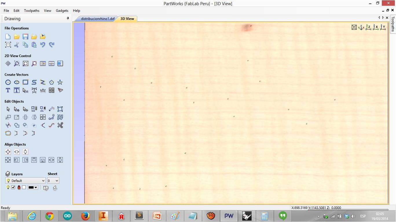
Photo 7:Simulation of the drilling toolpath The next step is to Make the cut profile toolpath, there are two options for this toolpath, make the cut inside or outside it will depend of your geometry and design. In my case I use only inside option, remember that the holes are milling with inside option too. So select the profile cut toolpath and then enter the parameters: "19.5 mm" of cut Depth (because the material thickness is 18.3mm), "6.35mm" milling tool, "Inside/left" option and in "cutting parameter" I introduced 7mm in "pass depth", that means the milling tool will pass 3 times with a depth of 7mm each time untill reach the 19.5mm. 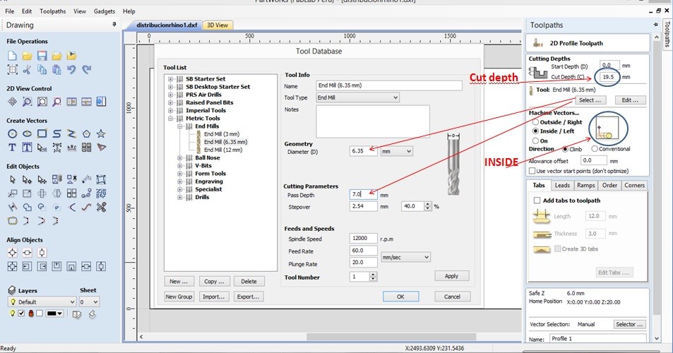
Photo 8:Making the Cut Profile After selected the curves for cutting you can simulate all proces in the same way we saw above. 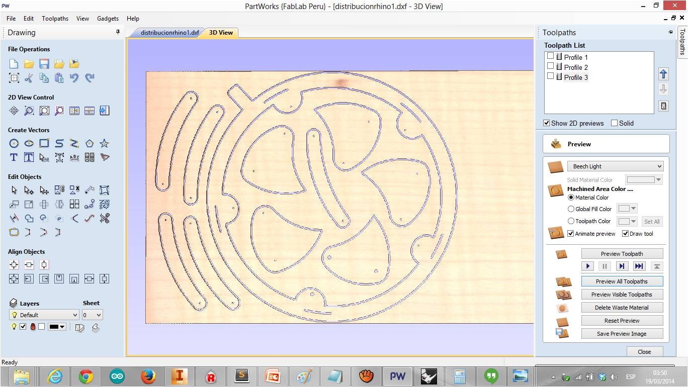
Photo 9:Simulation of the cut profile toolpaths Now we are ready to use the machine!. First of all we have to calibrate the Z axis, on Shopbot Console, click on cuts-Zero Z Axis/Zero plate,then put the plate of the Z axis on the board just below the milling tool , then click "OK" 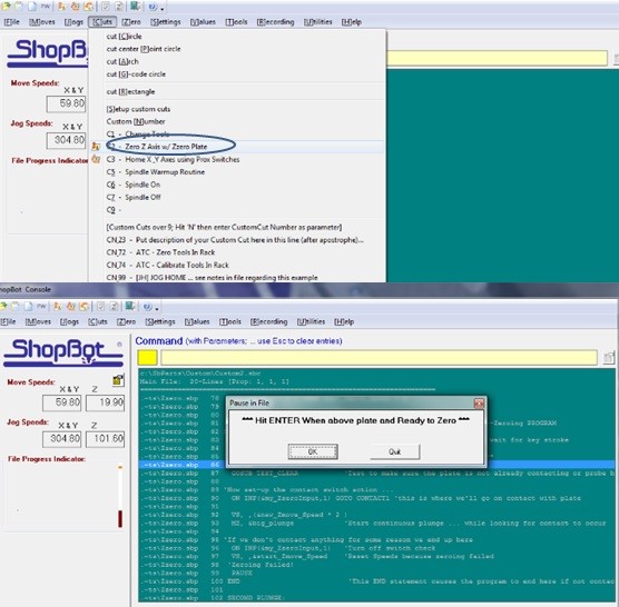
Photo 10:Calibrating the Z Axis After that,calibrate X,Y axis just by clicking Cuts-Home X-Y Axes using Prox Switches. Once the Axis were calibrated we can load our files: click on File-Part file load, and then click on start!....enjoy! 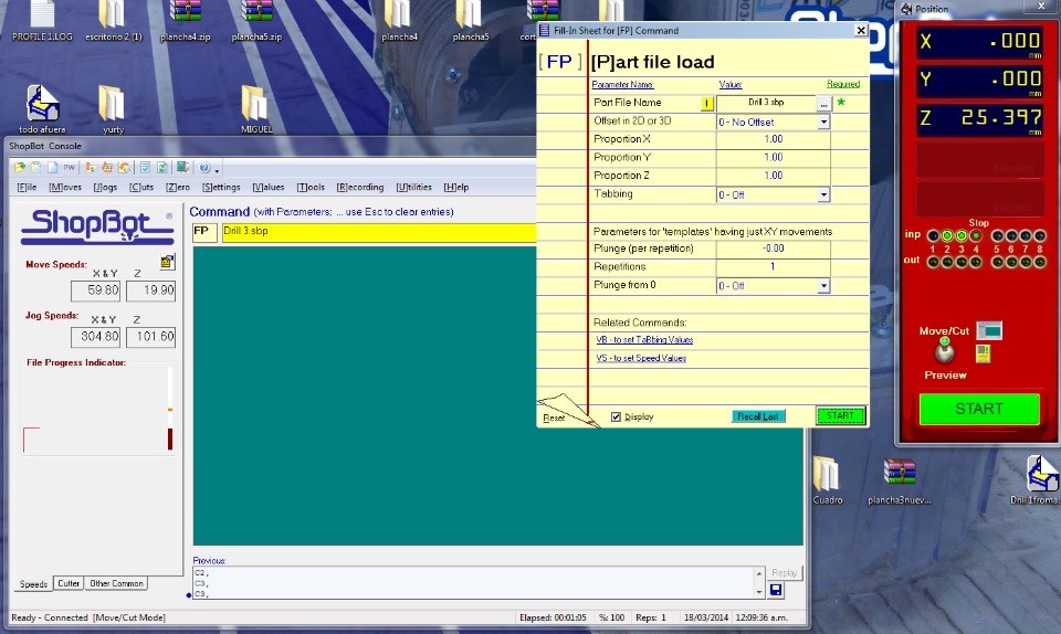
Photo 11:loading our files 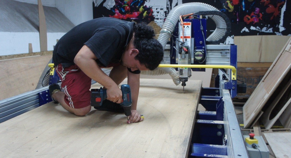
Finally...
Final comment:It Is necesary to do tests to calculate the tolerances of your material because they even could vary with the thickness of the board. Files: Mediafire https://www.mediafire.com/folder/19raivp99el7l/ccmGithub https://github.com/lefolindo/CCMachining |