 |
|
 |
|
Make a press fit system means that you must design and build a structure considering the mechanical tolerances in the process in order to assemble it without glue, screws or any other thing. For this assignment I have to do a pressfit system using the lasser cutting machine and I have to experiment until get the parameters in order to obtain a stable structure. Arduino is an open source electronic hardward which is very popular in the maker community. It is used to program microcontrollers in a simple way and it is very common use it with a protoboard where you can prototype a circuit and test your arduino programs. So I decided for this assignment to design and build an arduino+protoboard pressfit case. 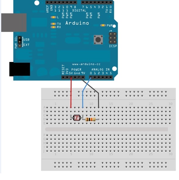
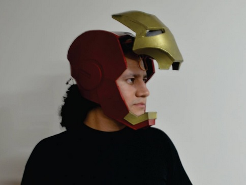
Photo 1:Arduino + protoboard The concept is to fabricate a case which could be used as a foldable portable case circuit. 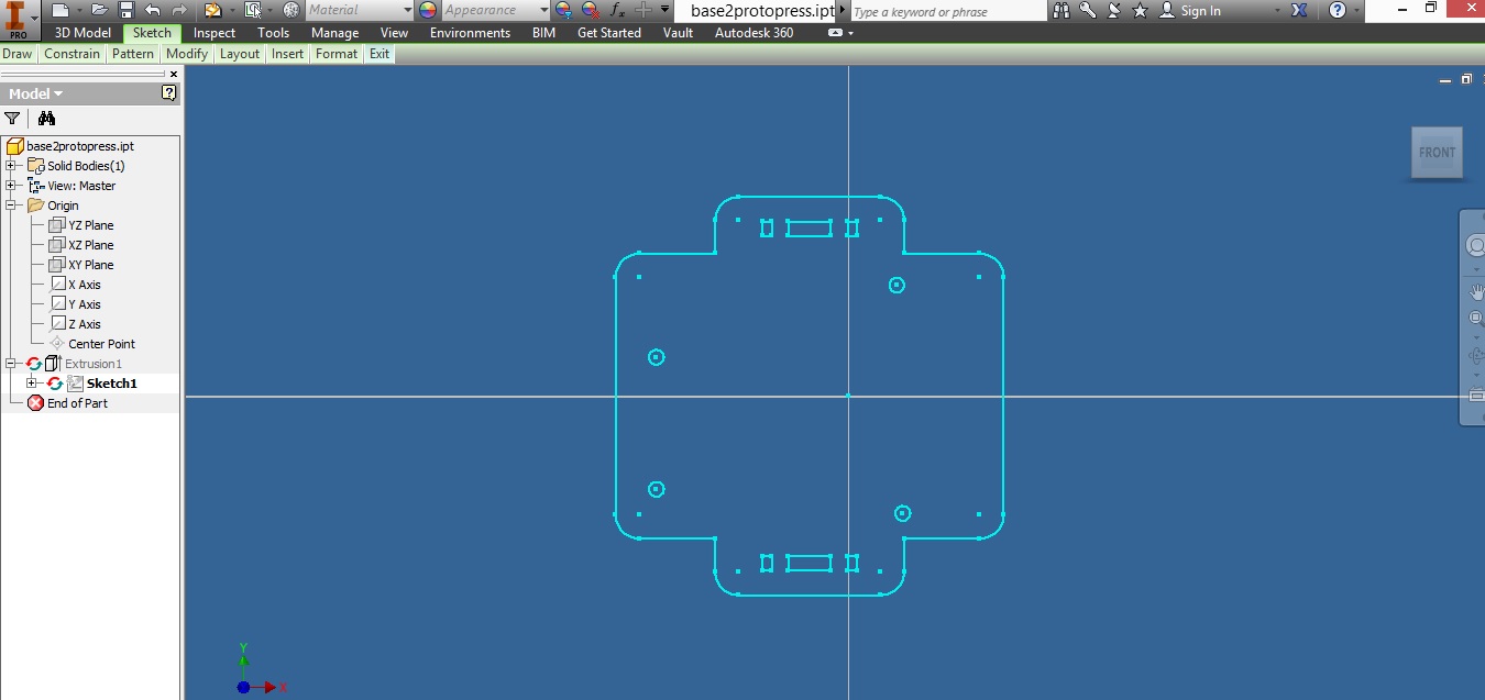
Photo 2:Inventor interface 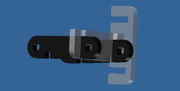
Photo 3:Assembly parts 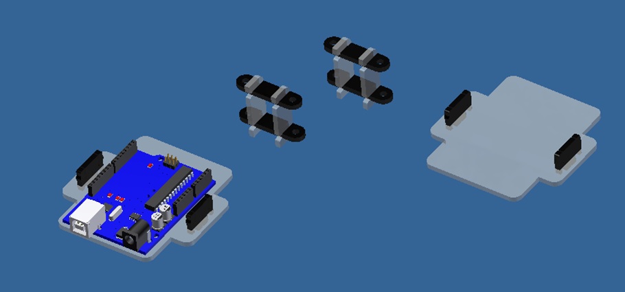
Photo 4:More Assembly parts 
Photo 5:Complete Assembly Then you can create drawing views and export them to dxf format to use with the lasser cutting machine: 
Photo 6:Drawing views 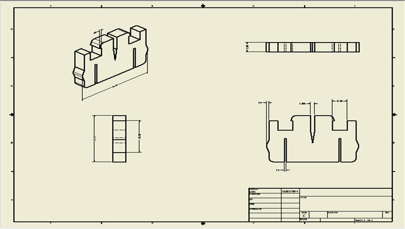
Photo 7:Pressfit bracket After doing some tests with the machine I found that the tolerances for acrylic 3mm width (no calibrated) is 0.2mm for pressfit. I recomend use calibrated acrylic because it has a uniform surface which is better for the pressfit conections . 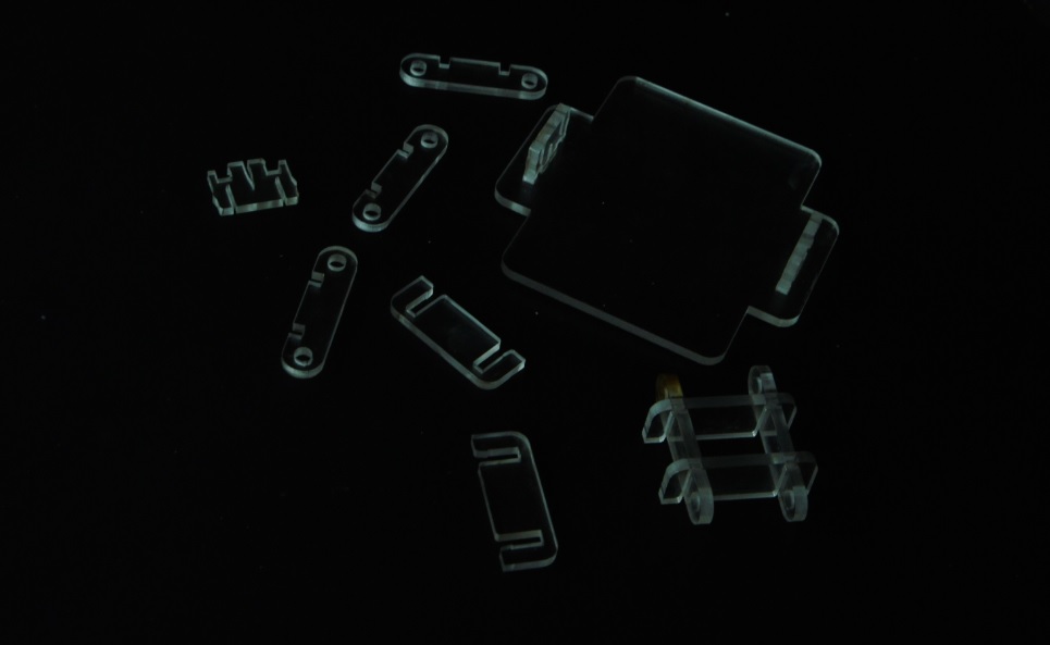
Photo 8: Laser-cut on acrylic Do not forget always verifying that the scale factor of the machine software is in 1:1,because the following may occur: 
Photo 9:Scale error 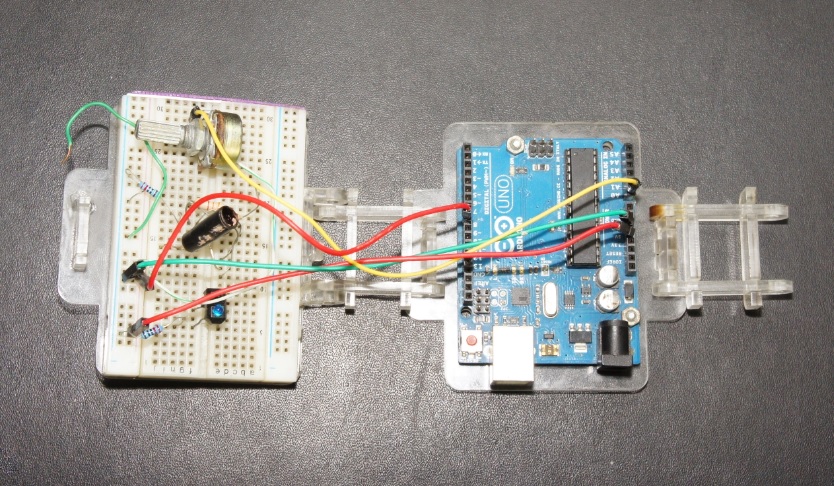
Photo 10:Real assembly open case + protoboard + arduino 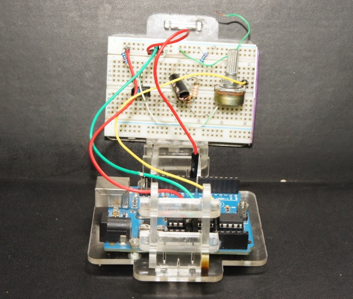
Photo 11:Folding 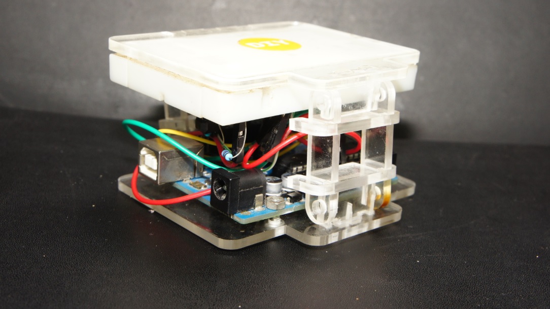
Photo 12:Folded Also I was playing with the vinyl cutter ... Files: mediafire https://www.mediafire.com/folder/i9lw3rdxmr6fv/cccGithub https://github.com/lefolindo/academy-cccSee you soon. |