 Fletch's Fab Academy 2014 Blog
Modifying a Tower Pro 9g Micro Servo for 360 Degree Rotation
The idea is to re-purpose a servo as a cheap alternative to a
gearhead motor. Note ince you have made this modification it
will be impossible to undo it and put your servo back to normal
operation.
The Tower Pro 9g I've used here can be found for under £3 from many
different suppliers in the UK. It's a small, light (9 grams),
cheap, easy to get hold of all over the world and has a high torque
output (Stall torque: 1.2 kg/cm at 4.8V). The only real issues
are that the plastic gears are quite cheap and so the servo
longevity under high loads will be an issue. However at this
price they are ideal for prototyping and can be onsidered throw away
devices.
There are two ways that this can be achieved:
1. Keep the existing control electronics in the servo.
Pros:
- No need for extra driver elecctronics external to the
servo. A PWM signal can be used to drive the servo
forwards, backwards or stop it.
- Only a single output pins is required per servo.
Cons:
- Number of PWM outputs on the AVR is limited, so solution
doesn't scale beyond a couople of servos without scaling to
multiple AVR's.
- PWM signal must be generated exactly in the servo 'dead' zone
to stop the motor rotating.
2. Throw out the existing control electronics and connect directly
to the motor in the servo.
Pros:
- No need for PWM outputs.
- Can easily generate a 'stop' rotation.
- If a PWM output is used the motor speed control is possible.
Cons:
- Requires an H-Bridge driver on the host PCB.
- Requires twice as many output pins on AVR.
I've decided to go with option 2 for my servo modification.
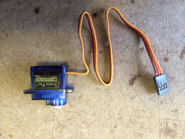
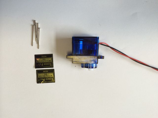
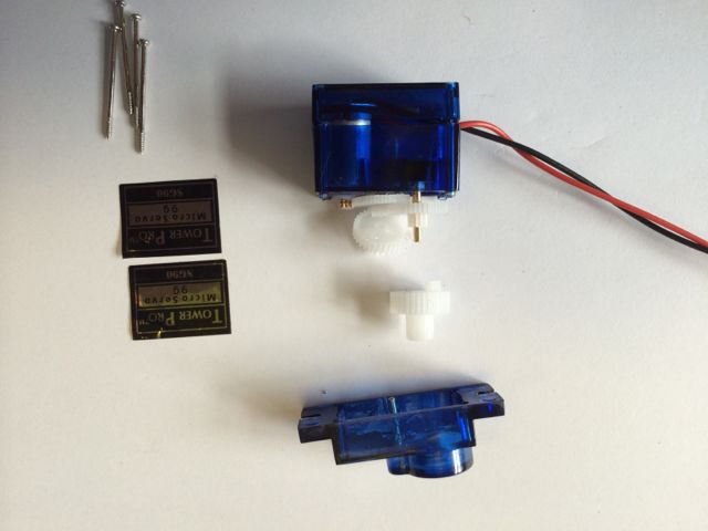
Tower Pro 9g servo before modification.
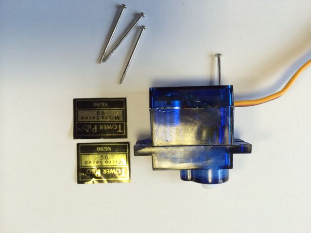
Step 1, Carefully remove the stickers and 4 small screws that hold
the servo together.
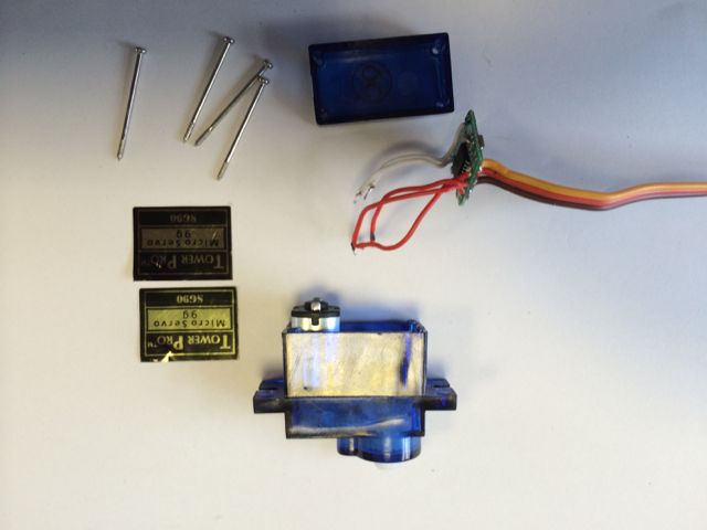
Step 2, Remove the base of the servo, de-solder and remove all the
internal electronics. Make sure to leave the potentiometer in
to servo as it acts as a spindle for the internal gears. The
electronics are mo longer needed, but the cable can be re-used for
later steps if required.
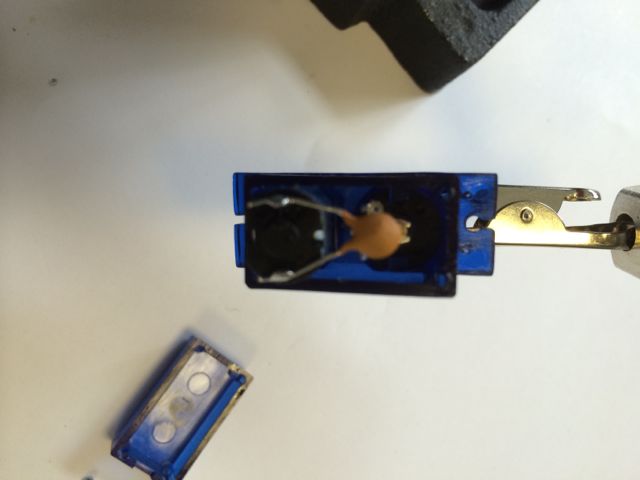
Step 3, Solder a 0.47uF capacitor across the motor terminals.
This just removes the electrical noise generated by the motor as it
spins.
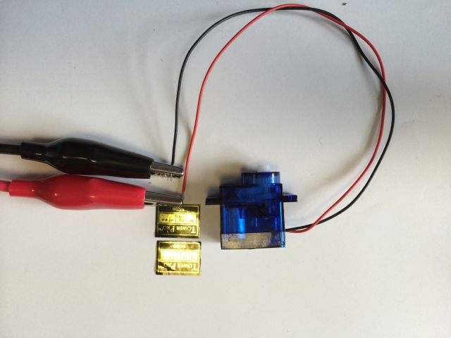
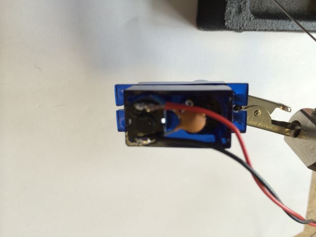
Step 4, Solder a pair of wires to the motor terminals. You can
re-use the wires from the control electronics if you want.
Step 5, Replace the cover over the bottom of the servo, don't screw
in place yet.
Step 6, Remove the top cover over the gears. Be careful to
note the location of the gears and not to disturb them. Note
that the metal spindle often comes away with the cover leaveing the
middle 2 gears loose. This isn't a problem, just be careful to
note where they go so that the can be put back correctly when
everything is re-assembled.
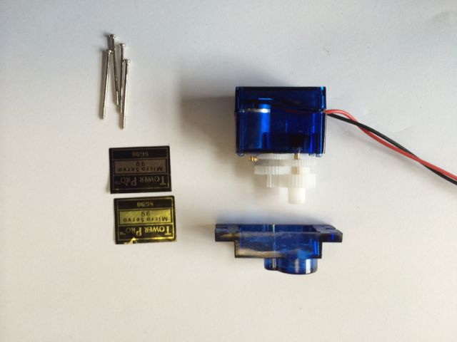
Step 7, Remove the final drive gear. This is press fitted to
the metal potentiometer spindle and requires slight 'persuasion' to
remove.
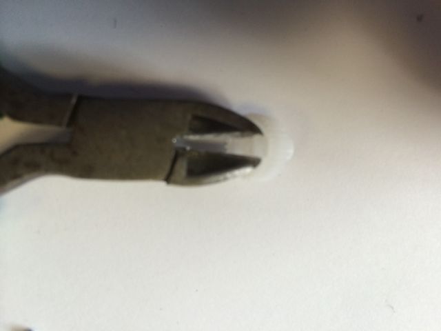
Step 8, Use a set of small side cutter snips to remove the plastic
'end stop' tab on the underside of the final drive gear.
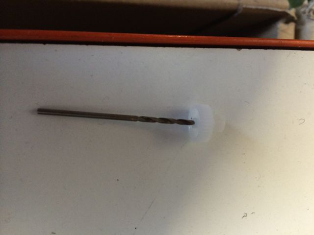
Step 9, Manually enlarge the hole in the center of the final drive
gear with a 2mm drill. This will allow the gear to spin with
no resistance on the shaft of the potentiometer. There is no
need to make the existing hole any deeper, only to enlarge it
fractionally.
Step 10, Re-assemble and test.