 Fletch's Fab Academy 2014 Blog
14. Mechanical Design, Machine Design
This weeks task was, "do the mechanical design for your final
project". My final project ( a swarm of very simple
co-operative robots) doesn't have a huge amount of complex mechanics
in it, so I set myself two tasks for this week:
- Work out the mechanics of the robot motion. My initial
idea is to use a very simple system of ungeared micro motors,
one driving a wheel on each side of the robot, with a skid or
castor at the rear of the bot. I would like to investigate
the 'pulling power' of this ungeared system to see if it's
fesible, if not then I'll need to investigate how to introduce
some simple gearing.
- Investigate the materials required to construct the 'e-ink'
style arena floor for my robot arena. My plan is to be
able to leave trails on the arena floor that other bot's can
follow. To do this I plan on having a magnet on the bottom
of the robot and a floor made up of cells filled with a mix of
white fluid and iron filings. The behaviour would be
similar to e-ink type displays. Initially the iron filings
would be invisible, having been pulled to the bottom of each
cell using a magnet from underneath the arena and the cell would
be white. As the bot passed the magnet on the bottom would
pull the iron filings to the surface of the cell, making the
cell turn dark.
In order to do both of these I need some parts that I've ordered, so
progress has been slightly limited.
14.01 Motor Pulling Power Tests
For my final project I'd like to keep the robots as simple, small
and light as possible. To this end I've ordered some tiny 20mm
x 7mm micro motors of the type normally found in small RC
Helicopters. These are yet to arrive so I did some preliminary
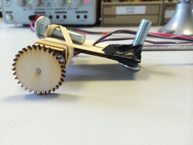
tests with the Jameco 1810099 12v motors in the inventory. I
laser cut a simple rig from 3mm ply on which I could add weight and
vary the wheel size (files here).
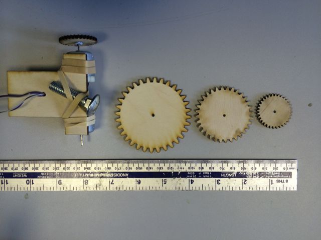
The wheels are actually involute gears that I stole from Mat
Keeter's gear.ko example. I had planned on writing a small
python program that could write out svg files with involute gear
designs based on input parameters. I did some research about
this before re-disoverinh Mat's gear.ko example that basically
already did everything I was planning to do! So the 'gears as
wheels' was more of a result of this work rather than any specific
design decision. In fact my arena floor will be a hard, smooth
plastic surface, these wheels would probably provide a good grip on
carpet, but very poor performance on the floor of my actual arena.
14.01.1 Test Setup
- My arena surface is likely to be clear acrylic, so I decided
to do the tests on the hard plastic tabletop rather than the
carpeted floor of the lab.
- I'm planning on using 3.7 LiPo batteries to power my final
robot design, so I tested the rig above with the bench top power
supply set to approx 3.5v.
- I used a large bolt to add weight and to provide a castor at
the rear of the test rig.
- I observed a run of about 1.5m across the tabletop.
14.01.2 Results
Not really a very scientific set of tests but the basic results were
as follows.
On a smooth table top the rig moved with all of the wheel sizes, but
it skidded around over the tabletop rather than moving in any
controlled manner. The more weight that was added the more
'controlled' the movement became.
On carpet the rig only moved with the smallest set of wheels,
sometimes the motors would stall completely.
14.01.3 Conclusions
Basically it only works with all wheel sizes on the smooth table top
because the lack of friction between the wheels an dthe surface
allows them to spin freely without the motors stalling. In
this state the wheel builds up and stores momentum, they will then
occasionally 'catch' on the surface and fling the rig forwards
producing the uncontrolled skidding or skittery motion.
On carpet the wheels don't get to spin up and store momentum, so
they only move at the lowest gearing ratio (smallest wheels) which
is border line stalling the motor.
To get any form of controlled motion I will need to gear the
motors. Possible options for this are:
- Use gear head motors. Pros: Would just work. Cons:
Most of these seem to be too big for the robot design I'm
proposing. Some smaller ones exist, I will investigate.
- Buy off the shelf plastic gears and make mountings eith laser
cut or milled from PCB sections soldered vertical onto PCB
chassis. Pros: ? Cons: Complicates the Chassis build.
Difficult to get all of the parts square?
- Laser cut gears from plywood. Pros: ? Cons: difficult to
cut gears on the small scale required due to laser cutter kerf
when cutting 3mm ply, could choose a thiner material.
- Modify a servo for 360 degree rotation. Pros: Simple
modification of a cheap device giving a complete package that
would be easy to mount. Cons: size may be too large.
14.01.4 Torque Calculations (ToDo)
Motor datasheet.
At 12v Motor max torque is 1.45mN/m with a stall torque of
7.16mN/m. Parameters at 3v are unknown.
ToDo Simple torque calculations regarding theoretical requirements
for gearing?
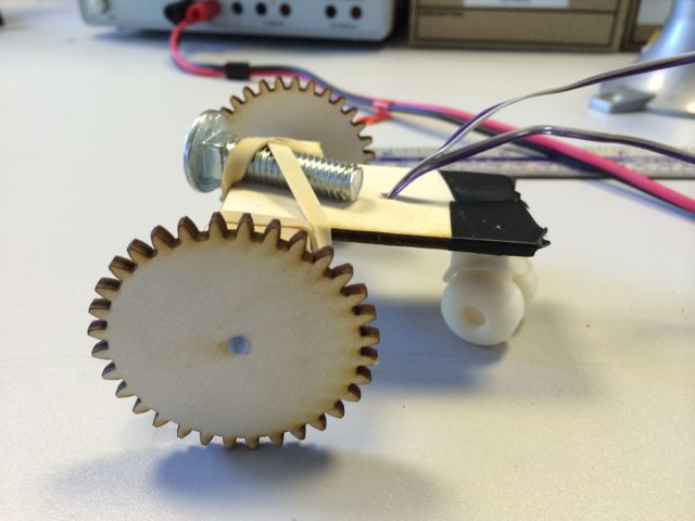
14.01.4 Plastic Castors!
Joel found a couple of 3D printed castors that had been manufactured
as a single part on the Dimension 1200, so we attached them to the
back of the rig.
14.02 Arena Design
For my magnetic-ink style arena I need the following:
- A white fluid that doesn't dry out.
- A method of dividing the space between 2 layers of acrylic
onto cells.
- A dark granular magnetic material
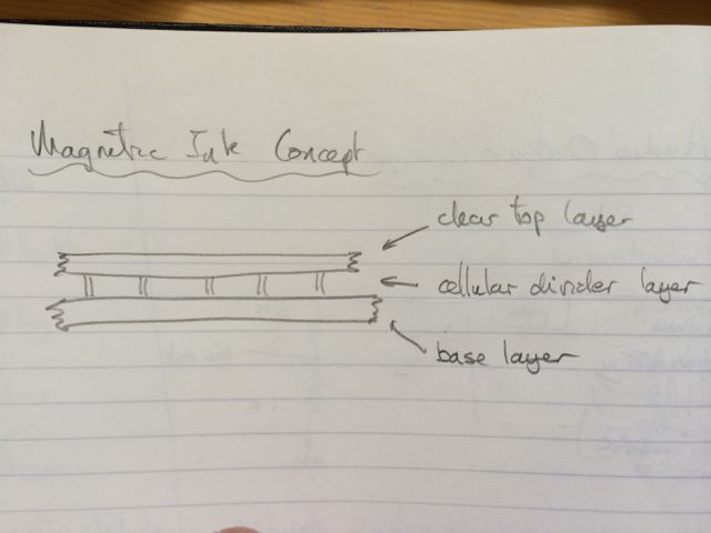
The idea is to sandwich the fluid between a top layer of clear
acrylic and a bottom layer of ply. The area containing the
fluid needs to be divided into cells so that all of the magnetic
material doesn't end up getting pulled to one end of the
arena. The area containing the fluid needs to be deep enough
that when all of the magnetic material is at the bottom it can't be
seen from the top.
14.02.1 Magnetic material choice
Initial thoughts for the magnetic material was to use iron
filings. The issues with is are:
They are quite large granules.
They may rust in any water based fluid
For this reason I have decided to investigate 'Magnetite' an iron
based ore. It should be possible to grind it down to a finer
powder. Waiting for this to arrive.
14.02.2 Fluid Choice
Vegtable oil mixed with white paint. Oil should inhibit the
rusting of any iron filings, it will also not dry out. Need to
investigate the type of paint, oil based paint my be best as water
based paints may not mix well with the oil:
- White powder paint.
- Ready mix white childrens poster paint.
- White emulsion.
Need to investigate mixing ratio of paint and oil.
14.02.3 Cellular Divider Material
Options:
- Net curtain material, may not allow enough cell depth.
- Expanded steel sheet.
Will need much more investigation when magnetite turns up.
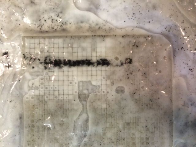
14.02.4 Tests of Magnetic Ink Arena Floor
I made a small scale test of the arena floor. It's messy and I
don't feel that it will scale well to make a full sized arena.
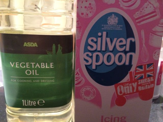
For the fluid I used cooking oil with icing sugar suspended in
it. For the magnetic particles I used magnatite
powder.
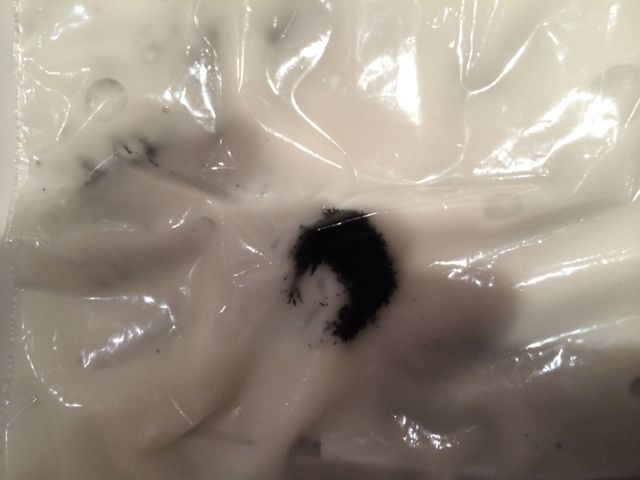
Test showing dark magnatite particles pulled to the surface of an
oil/sugar suspension with a magnet.
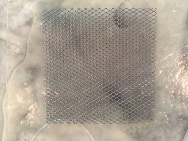
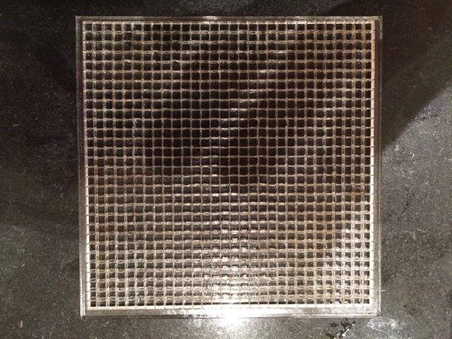
For the cellular divider I tested a few options but ended up with a
laser cut a grid of tiny squares into an acrylic sheet. This
is quite a time consuming process as the heat builds up in the sheet
and the waste part of the sqaure tends to re-bond to the sheet,
requiring each square to be snapped out with a pointed tool after
cutting.
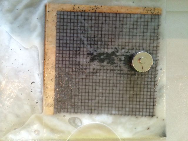
Tests with a wooden grid (grid is too visible through fluid) and a
steel sheet (edges too sharp and likely to puncture bag).
Tests with and acrylic grid.
14.03 Fun With Linkages
With any spare time I decided that I'd like to have a play with some
mechanical linkages. I'm particularly intrigued by Theo
Jansen's 'Strandbeest' designs. I'd like to laser cut some
basic linkages with movable pivot points to demo the linkage shown
here http://www.mekanizmalar.com/theo_jansen.html.
14.0X Other Issues
I discovered that I was getting pixellated copies of objects when I
cut and pasted (Ctrl-C , Ctrl-V) them in Inkscape on my Mac.
Everything works OK if you use 'Duplicate' Ctrl-D instead.
This page describes the issue http://wiki.inkscape.org/wiki/index.php/Frequently_asked_questions#Copying_and_pasting_in_Inkscape_creates_pixellated_images_instead_of_copying_the_vector_objects
which is to do with copy / paste going between the Mac and X11
clipboards when the Mac clipboard doesn't understand SVG data.