 Fletch's Fab Academy 2014 Blog
13. Networking and Communications - Laser Tag!
This weeks assignment was to "design and build a wired &/or
wireless network connecting at least two nodes." I'm intending
to use IR communication for my final project and so I decided to
test this by making a 'Laser Tag' game.
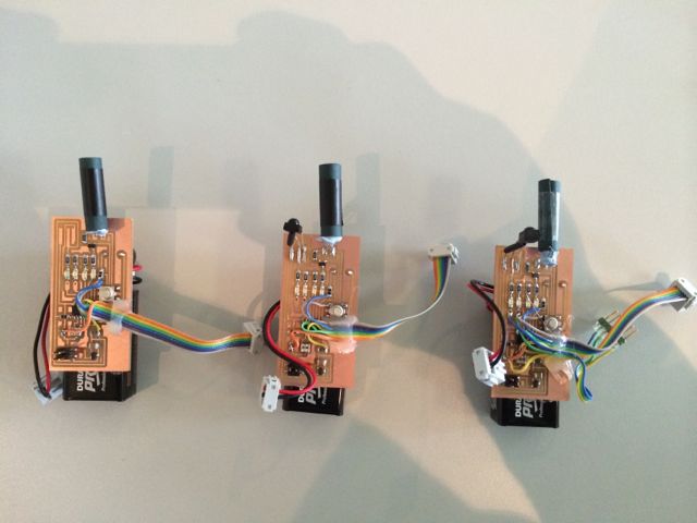
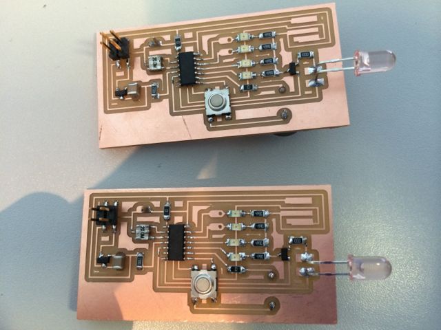
Three Laser Tag Network Nodes, one is also wired with an RS232 port
to use as a bridge node to the PC so that scores and tag statistics
can be reported. Design files are lower down the page.
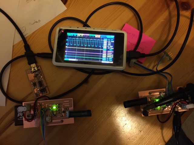
Me and Mike testing the Laser Tag in the Lab.
Fab Lab Laser Tag from James Fletcher on Vimeo.
13.01 Conclusions
It works, but the range is rubish and the error rate huge!
More time is needed to finish the software to demonstrate all of the
features I intended.
Thoughts on why range is so poor...
- Rubish encoding scheme.
- Bit lengths not matching IR reciever spec.
- IR Rx unit with unknown carrier frequency may not match my
modulation. The parts I actually ordered didn't arrive in
time and I ended up using some unmarked IR receivers scavenged
from a dubious source.
- IR LED 880nm but IR Rx 940nm.
13.02 Design Criteria
Nodes should be addressable. With support for 15 addresses and
one 'broadcast to all' address. Nodes should be able to keep
tally's of which other nodes have shot them. These tallys
should be reported to a PC at the end of the game for overall score
calculation.
It should be possible to start a game, end a game or reset nodes
from the PC.
The physical design would need:
- IR transmit / receive.
- LEDs to show 'health'.
- Buzzer for feedback.
- Switch for trigger.
- Battery power.
- Minimal extra connectors, so decided leave off ISP header and
program with 'clip' direct to ATTiny44A.
After a quick read through the RC-5 spec for IR remote controls
there were a few obvious take aways:
- Signal needs to be modulated with a carrier to distinguish it
from the background noise.
- Bit encoding scheme needs to include at least one transition
per bit (a Return to Zero code or Manchester code) allowing self
clocking and stopping the AGC in the receiver from being
swampped (see test below).
Carrier modulation in the AVR is OK, it's just a squarewave at a set
frequency.
Carrier de-modulation could be more of an issue, it would require
detection of the carrier and gain control of the receiver
stage. Carrier detection could be done as a digital signal
processing task. However gain control is more difficult,
requiring either analog sampling of the signal from an IR photo
diode, modification of the bias on the diode or control of an opamp
stage. I did briefly look into doing these tasks myself in the
AVR, but dedicated receiver chips such as TSOP2238
and IRM-3638T
are so cheap (sub $1) that it seemed rather pointless to waste my
time and AVR CPU time on solving the problem.
13.03 Initial Signal Tests
I did some initial signal tests with an unlabled IR receiver chip (I
think it's an IRM3638T) on an Arduino. I looked (not very
scientifically!) at the following:
13.03.1 Ability to Modulate a Basic Squarewave Signal and
Receive it Full Stop.
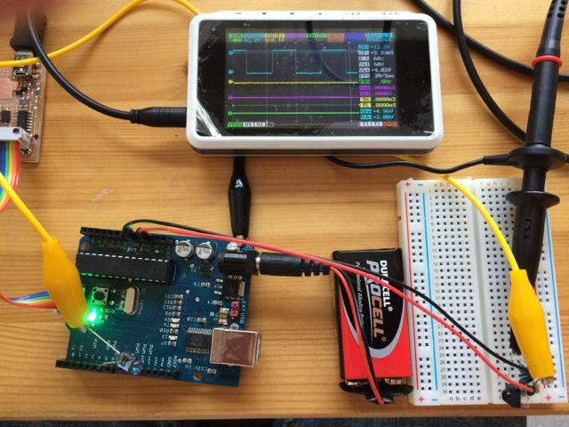
This was the first issue I had. I was squirting out a 38KHz
carrier modulated with a steady 500Hz 50% square wave via an IR LED
from the fab inventory. However nothing was coming out of the
receiver! I had a small IR remote control designed to work
with the receiver chip I had. The signal from the remote
showed up at the receiver output.
After lots of head scratching I eventually noticed that if I blocked
the beam it worked briefly when I allowed the beam through
again. I turns out that the AGC circuit in the receiver was
saturating, it needs pauses between bursts of data for the ACG to
recover.
Once I did 200ms bursts of modulated carrier and 1000ms pauses
between them the signal came out of the receiver perfectly.
My basic rx test rig:
13.03.2 Transmission Distance.
I seperated the rx and tx sections and carried the rx unit around
the room. I managed to see a signal out of the rx at distances
over 6m. However I was only looking for a squarewave out so
actual signal quality was unknown at this point. To achive
this distance I had to push the IR LED drive current up to around
40mA. The rx unit data sheet suggests ranges of up to
20m are achievable.
13.03.3 Beam Reception Angle of the Receiver.
At distances of around 1m I twisted the receiver with respect to the
transmitter. When they were 90deg out so that the tx beam was
hitting the side of the rx unit I was still getting a squarewave
out.
13.03.4 Effect of Beam Collimation With a Simple Cardboard Tube
Around Transmitter.
Next I tried collimating the tx beam with a simple cardborad tube
and looking at how far 'of axis' I could move the rx unit before
loosing the signal. Initially this didn't seem to have much
effect until I also plugged the back of the tube with BluTac.
Moving the rx unit more than about 20 degrees off axis caused the
signal to be lost.
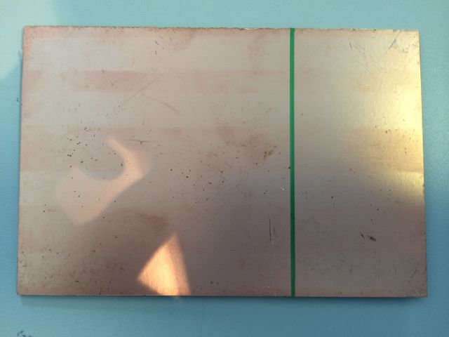
13.04 Inital Design as a Gun Shaped PCB
Initially I tried to mill a double sided gun shaped PCB complete
with 3x AAA batteries in the handle. This required working out
how to get the registration between the top and bottom
surfaces.
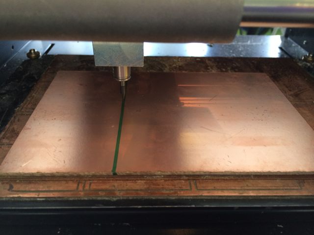
I stuck the stock double sidded copper board down with the lower
edge parralel to the bottom of the bed on the Modela. I milled
the bottom traces first, including some registration marks at the
boundary of the PCB. I then carried these marks to the edge of
the stock board and around to the other side, before flipping the
board left to right and sticking down parallel to the Modela bed
again. I then zero'd the bit on the center of the registration
mark. This way I was only having to deal with registration in
the x direction between the two sides of the board.
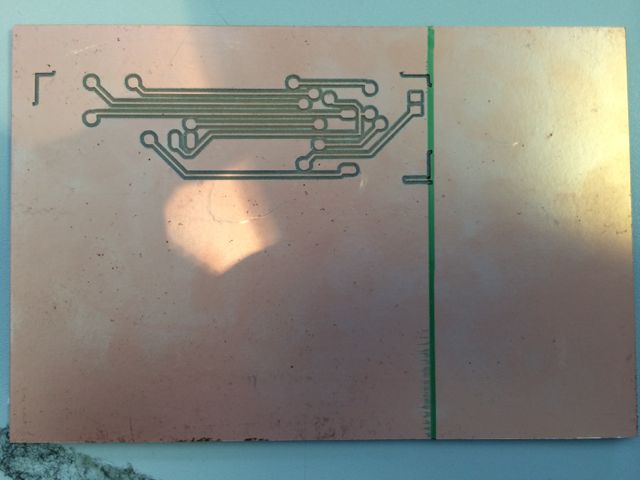
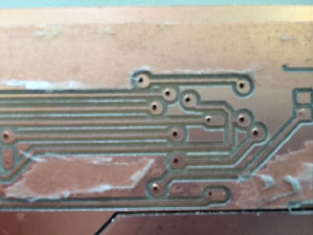
The registration between the top and bottom surfaces was OK as can
from the through holes on the via's in the photo below.
However ultimately this PCB design was a failure as the bed of our
Modela doesn't seem to be that flat and I couldn't successfully mill
a PCB that covered most of the bed. To get this one working
PCB I went through 3 of the 1/64inch bits! Need to re-level
the bed before continuing with this experiment. The PCB's also
end up with sticky tape on both sides which can be a mess to clean
up.
13.05 Second Board Design
I decided to make a much smaller single sided board design, but by
this point I was running out of time and starting to rush so I
forgot to add the resonator! Fail! Decided to get some
sleep and attack it with a clear head the next day.
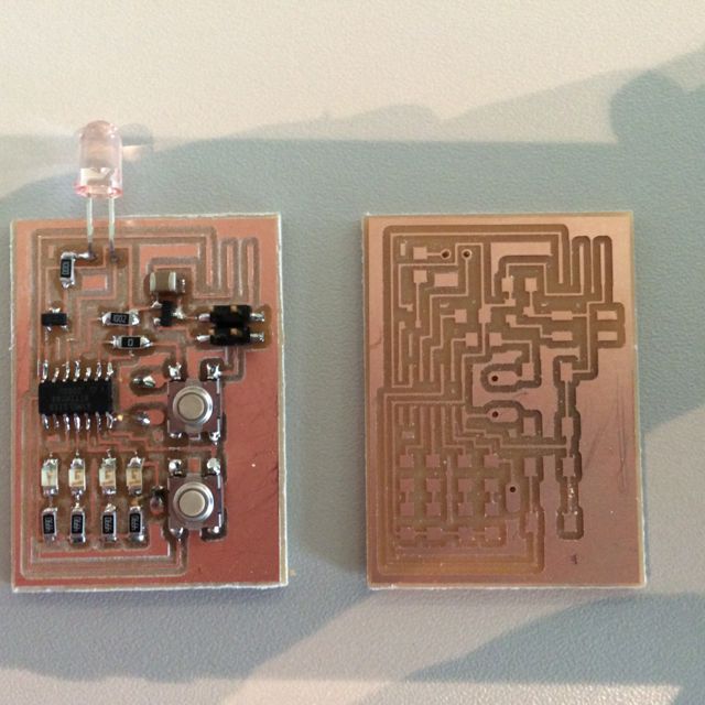
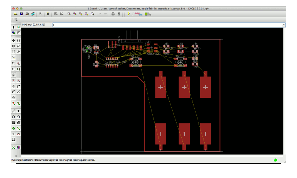
13.06 Third and Final Board Design
Third time lucky. Eagle schematic and board files are here.
Initially I had planned to program the boards with the 8 pin clip
direct to the ATTiny44a. Even though the clip only has 8 pins
and the AVR has 14, the clip will cover all of the required pins
except GND, so I just added a seperate GND test point to the board.
Using this method I just couldn't get reliable connections to the
AVR. I'm not sure if it was because the clip was designed for
an 8pin package, close inspection looks like it should still contact
the required pins OK. I suspect that it's due to the lumpy
soldering on some pins causing the clip to stand off slightly.
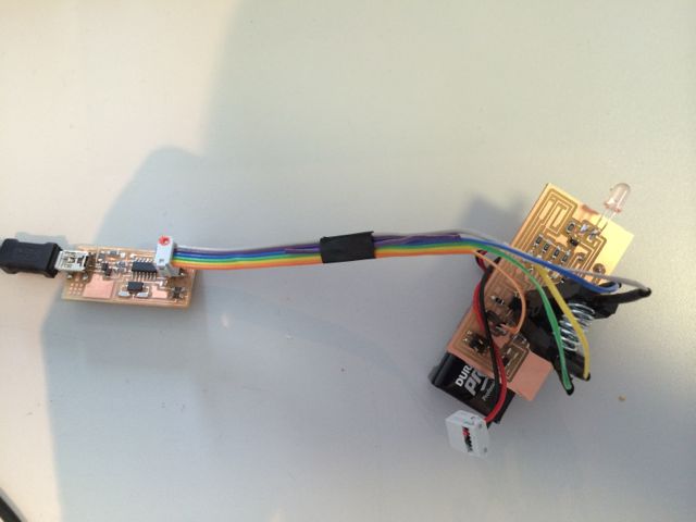
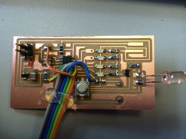
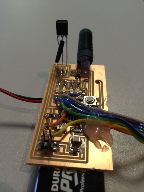
As I was pushed for time I just soldered a programming cable
direct to each board. Note that the IR receiver isn't fitted
as I was still waiting for the parts delivery.
Final board with collimated IR LED and BluTac to plug the hole at
the back of the cardboard tube.
13.07 Software Development
I had really run out of time by this point and soo decided to keep
it really simple. Code is here.
I had planned to implement address allocation via a broadcast
message to the PC, this was dropped.
I had planned to implement media access control by loooking to see
if the channel was busy to avoid collisions, this was dropped.
I had planned to implement multi-byte messages, this ws dropped.
I had planned to implement a PC bridge node, this was dropped.
The units do look for a valid communication, they buzz and decrement
the players health if the player gets shot. They only fire
when the player has health and fire twice per second if the player
holds the trigger.
Modulated carrier signal on scope and communications tests:
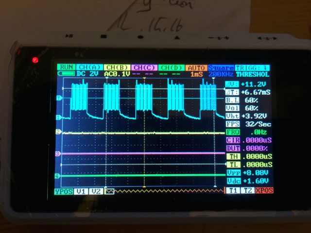
The major problem I've had at this point is the bit error rate, as
the range increases beyond a couple of meters the error rate rises
dramatically and makes communication impossible.
13.xx Design notes - Bit of a brain dump and not yet formatted
into anything coherent.
I've started using this weekly page to keep notes as I design, so
that I can write up more easily later. Nothing below this
point is formatted, it's just my notes.
IR comms
looked at doing de-modulation myself. Can do demodulation
OK, but AGC would be complex. At that point it just becomes
cheeper and more reliable to buy the off the shelf part
Vinyl Cutter 2 Layer PCB Test
To Add Vinyl cutter as a raw printer on Mac, start cups admin
interface on MAC - localhost:631
Add Roland GX24 as a 'raw' printer with the name 'vinyl'
Works from fab modules
To make Via mask export tStop bStop
Nodes are:
Gun x3
Bridge to PC x1
Required features
Media access - collision detection - collision avoidance (back off
by random amount?)
Message framing - message addressing - message error checking
IR Test
setup timer 0 to generate as close to 38KHz as I could get
16MHz / 8 = 2MHz / 53 = 37.735KHz, then cycle that on / off at 2ms
intervals by disabling OC0A
At first I tought not working, but then I notice some signal after
blocking the beam. Rx ACG seems to block signal if it's on for too
long.
=> must use a RZ coding to stop AGC cutting out signal
Use Manchester coding as per RC5
Rx unit is http://www.everlight.com/datasheets/IRM_3656T.pdf
(38KHz carrier - I had some of these lying around to test)
or TSOP2236 http://www.farnell.com/datasheets/30485.pdf (36KHz
carrier - this is what I ordered for the assignment)
Rx unit Expects > 10 carrier cycles to lock on (260us minimum
pulse)
Claims 6m rx distance at 45deg off axis
Expects 400 - 800us pulse width
expects 25mS between messages (assume for ACG to recover)
Rx unit is quite directional according to datasheet at 80deg it's
10% of the on axis sensativity. Mount tilted a few deg
towards the front of the gun?
What should my bit timing be? if bit timing is 800us per bit (1250
baud) then edges will be either 400us or 800us apart.
A 5 byte (40 bit) message would take 3.2ms to transmit - This is
probably Ok from the point of view of collisions when there are 4
nodes. Also as it's the recommended rate is probably OK from
the point of view of errors.
How will I detect incoming bit stream
Option 1) use sw to time the rate at which edges arrive.
Need to check a timer or count in a delay loop between pin
changes. Would consume all PCU time not allowing fancy
flashing LED's etc.
Option 2) use timer1 input capture to time rate at which edges
arrive. Frees up CPU time but consumes a timer that may be
needed in future swarm bot project. A software IRQ every
400us to possibly change the edge state and provide an app tick
would be acheivable. Input could drive INT0 and check the
current timer value to read data. CPU load would be very
high during tx
Option 3) Alternatively we could use the SPI output to mux the
carrier on/off. Doesn't support NRZ encoding, but may not be
a problem for such short messages.
Option 4) Use the SPI at double the data rate and encode the bits
into a pseudo NRZ pattern. Requires a Timer for baud rate
generation. Not very good at async reception due to lack of
ability to detect start condition well.
Option 5) Move to ATMega and use USART
on 400us irq -
inc tick count by 1, 2 or 3 depending on last bit count timing?
check tx bit count, shift bit out if required by setting up next out
compare timer
message format similar to IP packet
SRC addr, DST addr, Length, target function, seq number (starts at
arndom, allows us to address b'cast packets back to correct
device), payload, csum
Need a b'cast address
Need functions for:
- address alocation
- shoot type 1
- shoot type 2
- shoot type 3
- report kill
- send score to server
- request score
- start game
- end game
Repeat all messages 3 times to aid reception? At what rate?
Do we have 2 Tx per node? collimated and broadcast?
Basic test - see signal (200 repeats of 1ms carrier / 1ms
no-carrier, followed by 1000ms no-carrier)
Range test - uncolimated, falls apart after about 2.5
meters. (680R current limit. Looks like 1.2V across
diode, therefore 5.5mA)
Re-try with 100R, works up to 6m with line of sight
Will require much lower resistor when running on 3v from 2x AAA
Colimation test. Not very scientific measurements. 25mm
long black heavy weigght paper tube (3 layers). 5mm of it behind
LED. Up close it gets the signal all of the time due to
leakage out the back and reflections, but further away, go more
than about 20deg off axis and it looses the signal.
Will rx run on 3v? yes runs on 3v3 form arduino, or 4.5v from 3x
AAA cells
Rx angle test. Up close it gets signal from all angles
AVR Resource allocation:
Timer0 (8bit) - generate carrier
OC0A (PB2) - carrier output
Timer1 (16bit) - time edges in rx signal, generate edges on tx
signal also generate in app ticks? may miss some but should be ok.
ICP1 (PA7) - rx signal in (page 106) or use in PCINT mode
OC1A (PA6) - tx signal? use out comp to modifiy carrier and update
tick count (also MOSI pin)