 Fletch's Fab Academy 2014 Blog
12. Output Devices
This weeks task was to "add an output device to a microcontroller
board you've designed and program it to do something". I liked
the video output board that Neil demonstrated and I liked the idea
of a challenge, so I decided to design a Fab Video Game board based
on this principle. Ideally I'd like the board to be able to
run old 8 bit style games from the 1980's eg. Tetris or Asteriods.
Based on my experience with the spinning top I decided that I needed
more FLASH than that available in the ATTiny44a, so I decided to
upgrade to the ATMega328 as we have those in stock here in the
Manchester lab. I also added 4 buttons for control. On
top of this the board would need an audio line output that would
feed the same monitor as the composite video out.
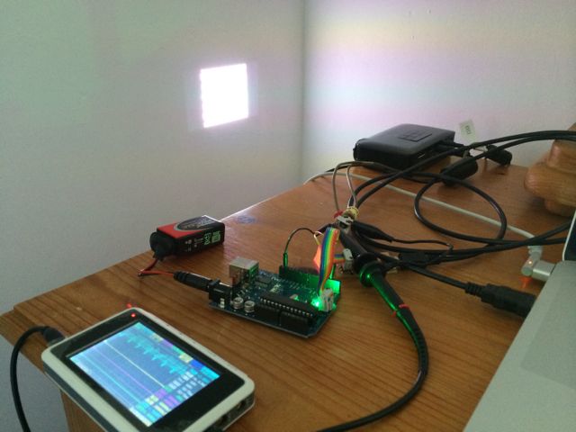
I didn't make it all the way to implementing Tetris, but the video
below shows a short demo running on my test board and a Pico PK320
projector. The image looses sync slightly as my line drawing
is currently taking slightly too long and corrupting a sync pulse.
FabLab video board demo
from James Fletcher
on Vimeo.
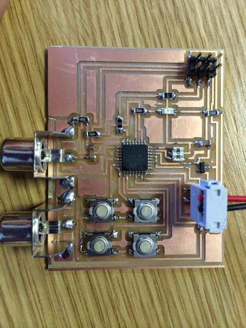
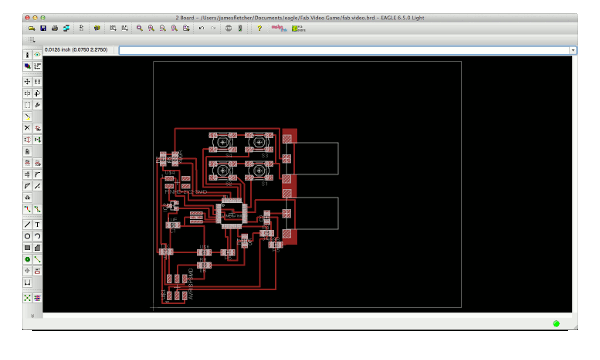
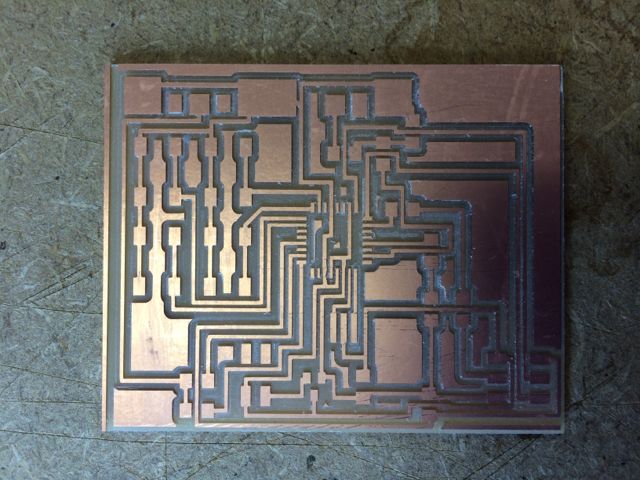
Picture of the final test board. I didn't have much time to
route it so I kept it simple. Ideally the board would have had
the RCA connectors along the top edge and the buttons along the
bottom.
12.01 Video Output
After looking at Neil's design I decided that the limiting factor
was the rate at which the state of the video output could be changed
by toggling the port pins in software. I decided that this
could be improved by using the SPI or UART pins to shift a bit
pattern out under hardware control. After looking at the
available byte framing on different hardware modules I decided to
use the USART in SPI mode for the following reasons:
- It supports 8 bit mode with no START, STOP or PARITY bits that
would corrupt the output.
- It has a 2 byte Tx FIFO that allows me to keep the Tx shift
register completely full with no gaps in the output bit stream.
- The baud rate will run right up to CPU_CLK/2
I used a PK320 Pico projector from Optima, as this supports both PAL
and NTSC I decided to stick with a NTSC format so that I could
initially start with Neils code to test the board. For my own
code I used NTSC timing info from http://www.astro.umontreal.ca/fantomm/Modedemploi/camera_guide_gene.pdf
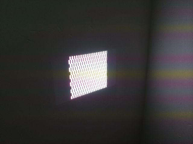
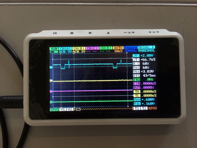
Early test pattern and sample video signal on scope.
12.02 Audio Output
The audio output is a simple line level out.
This is roughly 1v peak to peak into a high impedance (approx 10K)
input. I use a simple voltage divider from a single PORT pin
to allow me to generate square waves between approx 0v and
0.5v. I then use a small dc blocking capacitor to remove the
dc component of the signal and smooth it slightly. Although
this square wave is far from a perfect audio signal it approximates
to a a sine wave at the same fundamental frequency with lots of
higher order harmonics.
I then use Timer0 in CTC mode to generate a square wave on OC0A and
this to drive the audio.
I transposed the tune from the sheet music on http://www.gamemusicthemes.com/sheetmusic/gameboy/tetris/themea/Tetris_-_Theme_A_by_Gori_Fater.pdf.
Frequencies for notes were based on http://en.wikipedia.org/wiki/Piano_key_frequencies.
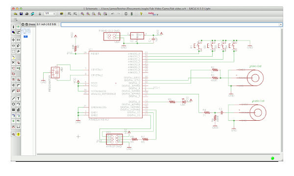
12.03 Design Files and Code
The Eagle schematic and
board files are
here. Along with the traces and interior png's.
The source code is here,
it will build and run on either a 16MHz ATMega168 arduino or my
20MHz ATMega328 test board.
12.04 Issues
12.04.1 The Case of the Failed PCB Milling
I saw a 'fabduino'
project online and noticed that this provided Eagle files using the
ATMega328 and png's to mill with the standard 1/64th bit. So I
mistakenly assumed that the ATMega328 TQFP 32 part in the Eagle fab
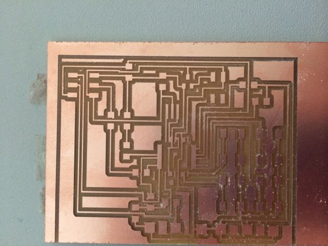
libraries was millable with the 1/64 bit. I was wrong, my
first attemp is shown below, note that not tool paths have been
generated between the pins of the TQFP package in the middle:
When I had come across this before I had found that a quick solution
was to lie slightly about the tool size to fabmodules. By
reducing the tool size slightly from 0.4mm to 0.3mm it will generate
tool paths for smaller gaps but all traces and pads will also be
slightly thinner as the tool will run closer to the outside boundary
of the pad or the trace. It's not the correct way to fix it
but it works sometimes as a quick fix. However for this board
I had to reduce the tool size right down to 0.2mm to get fabmodules
to generate all of the tool paths between the pads. This is
far too far from the real tool size and the final traces are too
fragile!
I investigated exporting at higher DPI from Eagle but this didn't
fix the issue. I also looked into using a smaller 10mil tool
and doing 3 passes on the Modela (10mill, 1/64inch and 1/32inch),
but this would have required more setup time than I had
available. At this point I ran out of time to mill boards
before the Easter break and so decided to prototype my code on an
Arduino whilst I investigated the problem in more detail.
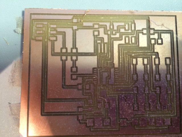
On closer inspection of the fabduino traces files I noticed that the
TQFP package didn't match the one in the Eagle libraries, the pads
were much thinner. Rather than create a new library component
and have to re-route my board when I swapped the package around, I
decided to manually edit the traces file in GIMP to remove some
copper between the pads.
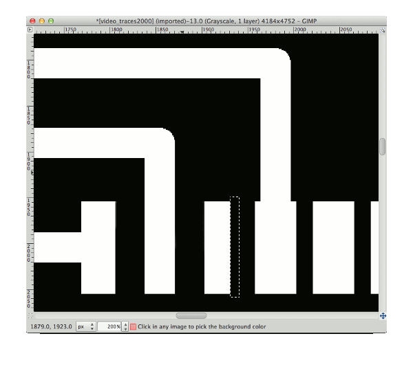
This finally produced a millable board.
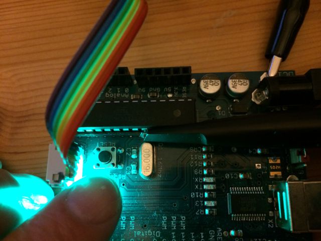
12.04.2 The Case of the Broken Fuse Bytes
When working with the Aruino I managed to flash some broken fuse
bytes at some point. This left the ATMega328 in a state where
it wasn't generating an internal clock and so I couldn't flash it
with the FABISP. To get around this I fed a clock signal into
the AVR on the TOSC1 pin whilst trying to flash and slowed the
FABISP bit rate by changing the programmer line in the makefile to
the following:
PROGRAMMER = -c usbtiny -B 1024 -e
Luckily my portable scope had a 200KHz square wave output that I
could use for the clock and just touch the scope probe to the AVR
pin whilst flashing. This only needed to be done once to
program sensible values back into the fuse bytes.
12.05 Thoughts on IRQ Response Time
Initially I thought I would use irq service routines from Timer1
driving a state machine to generate all of the video timing
information rather than spinning in a polling loop waiting for flags
to change saying that a count had expired. This would allow
for a better separation in the code between the NTSC signal
generation and other work such as gameplay. However on
investigation I discovered that the irq response time is too poor to
meet the 5us timing requirements around the sync pulses. A
basic irq routine in C and compiled using avr-gcc with -Os comes out
at over 40 cpu cycles when you include the time it takes too enter
the isr routine. This alone is 2.5us at a 16MHz clock.
For this reason I fell back to using a polling method to check the
timer and generate the video signal.
With effort this could be improved. Some registers could be
reserved so that the compiler didn't use them. Then dedicated
asm routines could get rid of a large part of the function prolog /
epilog and avoid stacking registers. However any pre-compiled
LIBC code could still use these registers causing other issues.
Another option would be to use a hybrid system, polling within and
isr for the timing around the sync pulses and using a more
traditional isr approach during the displayable portion of the line
to allow easier singal generation / gameplay work division.
IRQ Response Time Analysis
// init
// Counts up in CTC mode
// No OC1x behaviour
TCCR1A = 0b00000000;
TCCR1B = 0b00001001; // CTC, 1 prescaler
TCNT1H = 0;
TCNT1L = 0;
OCR1AH = (_VIDEO_hsync_front_porch >> 8);
// initially set timing to full line width so we avoid any early
irq's
OCR1AL = (_VIDEO_hsync_front_porch & 0xff);
TIMSK1 |= (1<< OCIE1A); // Enable timer 1
compare A irq
ISR(TIMER0_OVF_vect)
{
VIDEO_state++;
if(VIDEO_state&0x01)
VIDEO_port = 0;
else
VIDEO_port |= VIDEO_high;
}
// Above IRQ code generates the following
assembly, numbers at the end of the lines are instruction cycle
counts.
90: 1f
92
push
r1
2
92: 0f
92
push
r0
2
94: 0f
b6
in r0, 0x3f ;
63 1 get SREG
96: 0f
92
push
r0
2 push SREG
98: 11
24
eor r1,
r1
1 zero into r1
9a: 8f
93
push
r24
2 push temp reg used by code
9c: 80 91 00 01
lds r24,
0x0100
2 load variable
a0: 8f
5f
subi r24, 0xFF ; 255
1 inc
a2: 80 93 00 01
sts 0x0100,
r24
2 store incremented variable
a6: 80
ff
sbrs r24,
0
1/2/3 skip if bit set
a8: 02
c0
rjmp .+4
; 0xae
<__vector_11+0x1e>
2 rel jump
aa: 1b
b8
out 0x0b, r1 ;
11
1 clear video port
ac: 01
c0
rjmp .+2
; 0xb0
<__vector_11+0x20> 2
ae: 59
9a
sbi 0x0b, 1 ;
11
2 set bit in video port reg
b0: 8f
91
pop
r24
2
b2: 0f
90
pop
r0
2
b4: 0f
be
out 0x3f, r0 ;
63 1
b6: 0f
90
pop
r0
2
b8: 1f
90
pop
r1
2
ba: 18
95
reti
4
Total 37 cycles
Simple code to toggle video out as we spin waiting for timer to
expire. This was one of my first test patterns.
/*
{
VIDEO_port_temp = VIDEO_port & ~(VIDEO_high | VIDEO_low);
VIDEO_port = VIDEO_port_temp | VIDEO_low; // set black: 0.3v
VIDEO_port_temp = VIDEO_port & ~(VIDEO_high | VIDEO_low);
VIDEO_port = VIDEO_port_temp | (VIDEO_high | VIDEO_low); // set
white: 1.0v
}*/
ToDo
- Finish Tetris
- Create a millable TQFP 32 part for Eagle
- Re-route the board with the RCA jacks and buttons in a better
placement.
- Optomise the graphics routines.
- Add font support.
- Add sprite support.