 Fletch's Fab Academy 2014 Blog
10. Input Devices
This weeks assignment was to measure something: add a sensor to a
microcontroller board that you've designed and read it. After
Neil's comment that the hall effect sensors were sensative enough to
detect the Earths magnetic field I decided to put this idea to the
test and build a spinning top that displayed text on a radial strip
of LEDs and synchronised the text display to the spin rate of the
top using the Earths magnetic field as an index point.
10.01 Initial Test Design of Fab Spinning Top
I put together a fairly quick test design based on a similar project
I'd seen before, using a circular PCB and a pair of CR2032 cells at
opposite sides of the board to balance it. I then intended to
use a bolt through the middle to provide a pivot point to spin
on. Here are the Eagle schematic
and pcb files for my first
attempt.
The batteries used are Radio Spares part number 597-368.
These were chosen simply because I had some laying around. The
design would benefit from being modified for a pair of standard
CR2032 battery holders.
I made the PCB as big as I could in the free version of Eagle,
around 3 inches diameter. I marked the edge of the board with
a circle in the top copper layer in Eagle before I did the
routing. I placed the batteries on opposite sides of the PCB
to balance it. I arranged the LEDs in a radial strip at the
top of the PCB.
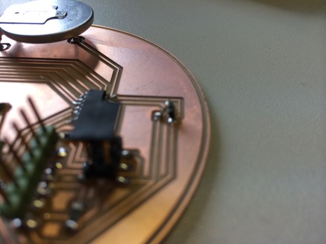
Note that the hall effect sensor is sensitive perpendicular to it's
marked surface, so it actually needs to be mounted vertically on the
PCB, using a small wire leg (see below).
I wanted as many IO pins for LEDs as possible, so I used an
ATTiny44a rather than a ATTiny45. However without multiplexing
or re-using the ISP pins I only had 5 LEDs, so I found this nice little 5
pixel high low res font that I could use.
I put together a couple of test bit of software and the first thing
that I discovered is that in it's basic form the A1302 hall effect
sensor in the fab inventory is no where near sensative enough to
detect the difference between North and South in the Earths magnetic
field. So as a temporary measure I used a strong magnet to
mark an index point. I used on of the built in Timers to
create a ticker that I used to measure the time of each revolution
and then converted that to RPM. Here is a quick video of the spinning top
in action. It's displaying revs per second as it spins.
Fab Academy spinning top
from James Fletcher
on Vimeo.
With the limited FLASH space for the font and time available I
didn't carry on to display complete user programmable messages with
this initial design. Code is here (it ain't
pretty or well commented as it's only test code).
10.02 Sensitivity Issues in Intitial Design
A quick and imperfect analysis of the issues I had with the
sensitivity of the hall effect sensor.
- Earths magnetic field varies from 0.25 to 0.65 Gauss
(according to Wikipedia which is of course always correct!).
- A1302 sensor in inventory has a sensitivity of 1.3 mV / Gauss
(at VCC=5v).
- ADC on ATTiny44a is being used in 10 bit single ended mode
with full scale VRef of VCC, this gives approx 5mV per bit
resolution.
So assuming worst case Earth field strength of +-0.25 Gauss between
North and South we would expect to see approx 0.65mV change on the
ouput of the A1302. We can only measure down to 5mV, so no
where near enough.
10.0.3 Other Issues with Initial Design
The initial design had some other issues that I would address in any
future versions:
- The batteries caught on the strong magnet used as an index
point as the board came to rest att the end of each spin.
This sometimes ripped the batteries from the board as the solder
pads were quite small. In future I'd add a large copper
pad here.
- The connector placement was a bit awkward and I damages all of
the connectors at some point, lifting traces from the PCB.
Hence the large amountss of hot glue in some of the images.
- 5 LED's isn't really enough, I'd multiplex and use more.
- The ATTiny doesn't have anough FLASH to store the whole
font. I'd probably change to an ATMega.
- The batteries are soldered onto the board as these were the
only ones I had available. I would look to get some
holders for CR2032's or use AAA cells on a slightly larger
board.
10.04 Proposed Design Sensitivity Improvement
If I was to use 2 hall effect sensors facing in opposite directions
to maximise the difference in the outputs and then feed this to the
differential inputs of the ADC I could also utilise the built in 20x
gain.
Also the original single ended input voltage was centered around
2.5V, meaning that I had to use an ADC Vref of VCC in order to have
the dynamic range to be able to measure the signal. As my
differential signal is centered around 0V I can now use a much lower
Vref (maybe the built in 1.1V reference) and consequently get a much
greater resolution.
In this case I would very roughly get the following input signal:
+- 0.25 Gauss from each sensor, therefore +0.5
Gauss when facing North and -0.5Gauss when facing South. At
1.3mV/Gauss this gives a signal of +-0.65mV. We may not be
able to measure the negative signal depending on the setup of the
ADC.
ADC sensitivity:
Vref 1.1V gives approx 1mV internal
resolution. 20x Gain gives roughly 0.05mV external resolution.
This should be enough to detect the Earths magnetic field as the top
spins, however it's quite a small signal and will be very prone to
noise!
10.05 Step Response Board
I decided to have aplay with the step response board as this is such
a versatile input device. I redesigned the PCB to add a couple
of LED's (reusing some SPI pins). Here are the Eagle schematic and PCB files. I left
large pads on the PCB to test with rather than add a connector for
external sense pads. I wanted to ultimately make this into
another message spinning device, but this time for a bicycle wheel,
using the step response to detect the chainstays or forks as the
spun past.
The LEDs on the test board are programmed to flash when the user
touches the pads. In order to get enough pins to drive the
LEDS and the sense pads on an ATTiny45 I had to reuse the SPI pins
for the LEDs. Code is here
(again it's only test code so not pretty).
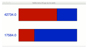
I also modified Neils python code slightly to show separate up /
down values so that I could better understand what's going on.
Python code here.
There is a lot more to investigate with this input device and I plan
to spend more time playing with configurations of sense plates and
the timing of the ADC conversions.
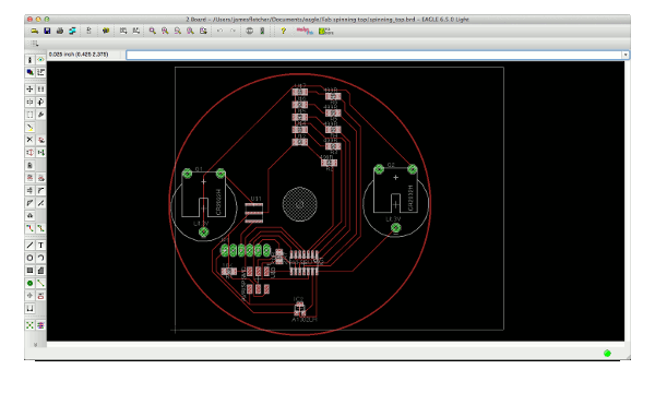
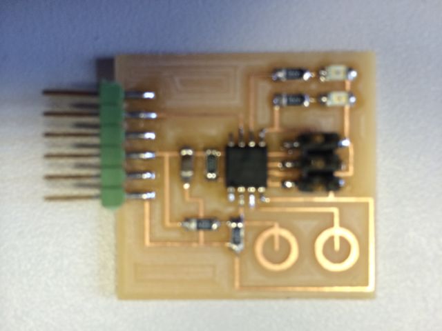
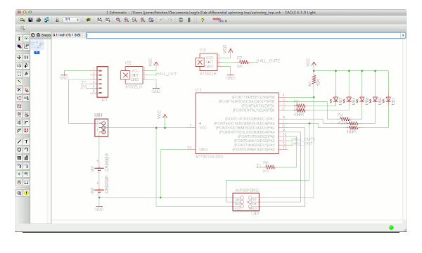
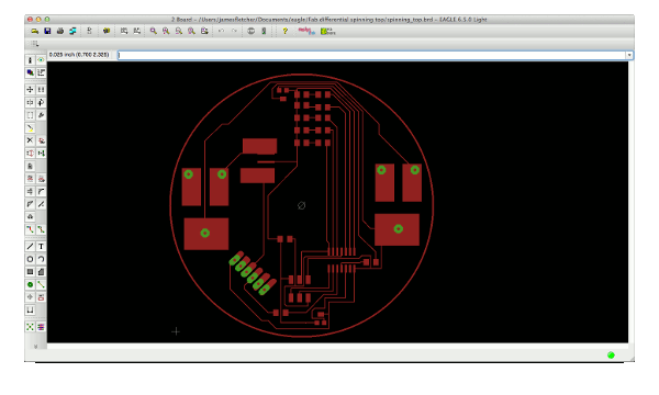
10.06 New Spinning Top Design
With the time left I decided to improve the spinning top design to
see if I could get it to detect the Earths magnetic field. I
added 2 opposing A1302 hall effect sensors and wired them so that I
could test using both the differential input of the ADC as already
described or try looking for zero crossing points using the Analog
Comparator. I also re-used some of the SPI pins for
LEDs. Eagle files sch, brd.
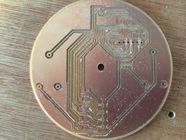
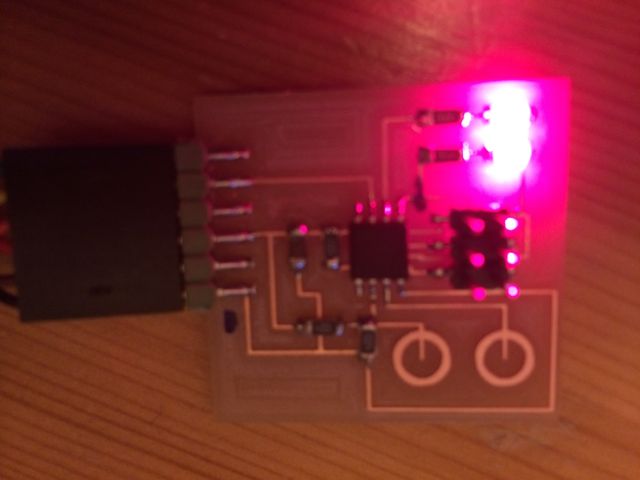
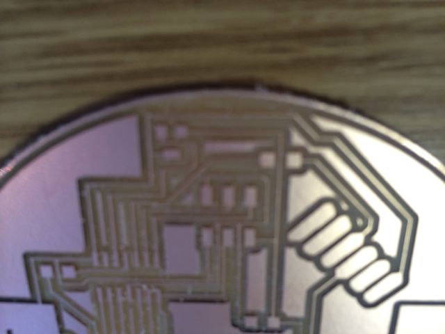
I've milled this board but the traces broke in a few places (see top
of image below, sorry slightly fuzzy). I'm in the process of
modifying and re-milling it.
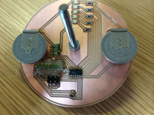
I've successfully made and populated the PCB for this new spinning
top design, but then run out of time to do anything other than basic
tests with the code. This will be re-visited when I have time
after the end of Fab Academy.