Week 7: Computer-Controlled Machining
Make something Big!!!
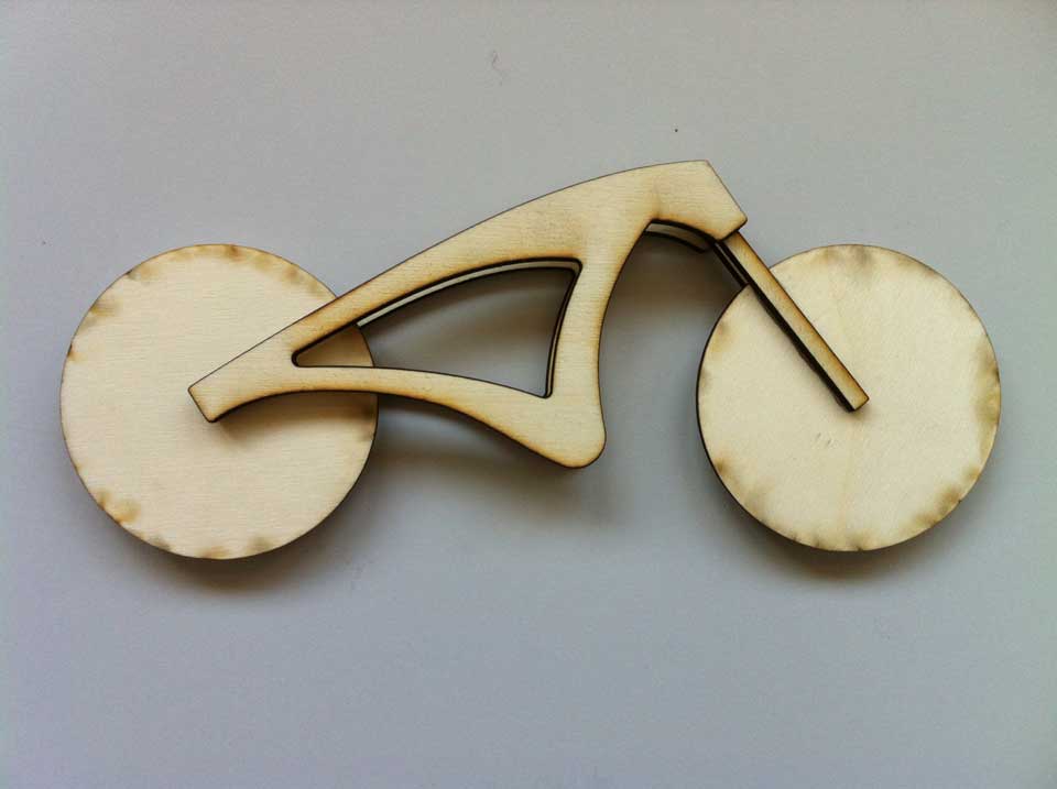
I got to admit that this was not an easy task. First of all I wanted to destroy my bicycle and redesign it. The idea was to change the aluminum bike frame for a wooden one making some adjustments on the existing parts in order for the frame to fit perfectly, but it was much more difficult than I thought. There are a lot of things to consider when fabricating a bike like the wheel and steer axis, gears and pedals. All of the components are cleverly designed to work in harmony so it is not that difficult to understand, although it seems something rather simple, that removing some of those parts and replace by another ones of different nature will not be an easy process.
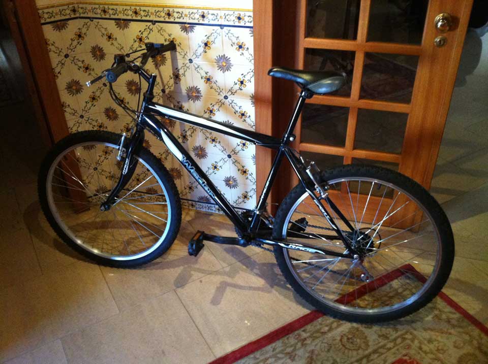
This is my bicycle and this was what I wanted to do with it:
I will put my hands on this project again as soon as I have time, because it is something I really wnat to do with my bicycle, but not in a week. There are many other projects I'm working on right now and I don't have the time to complete this in time.
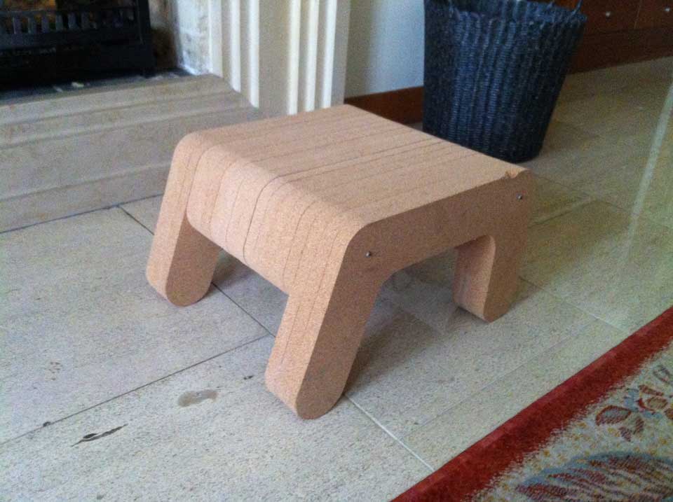
A Cork Stool
Since the bike idea was not suitable to work on this week, I began to worry on what I was going to do. My mind was blank and I was not getting anywhere. Luckly, my instructors Ferdinand Meier and Luís Carvão encouraged me to think on a chair design, in which I could get inspired on a software developed called Sketch Chair, or think about the work on the famous Layer Chair by Jens Dyvik.
I started to think on their suggestion and at the same time researching for both in order to determine which way I was going to follow. After a day experimenting with the software and looking into the Layer Chair, I decided to take the path on layer construction and got me thinking, what can I do different?
Since everyone were using wood for their projects I thought that making use of some cork I had at home, could be the difference I was looking for, the material. But what was I going to do? I thought of my mother and her love for stools, and so I designed something that would be helpful to her when she wants to rest her feet or sit near the fireplace where she likes to smoke her cigarrete, or simply help her reaching higher heights, like the kitchen's top cabinets.
The Design
Drinking from the juice that the Layer Chair gave me, I based my design on the same lines. I started to sketch the stool's legs and I came up with this profile:
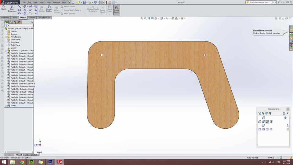
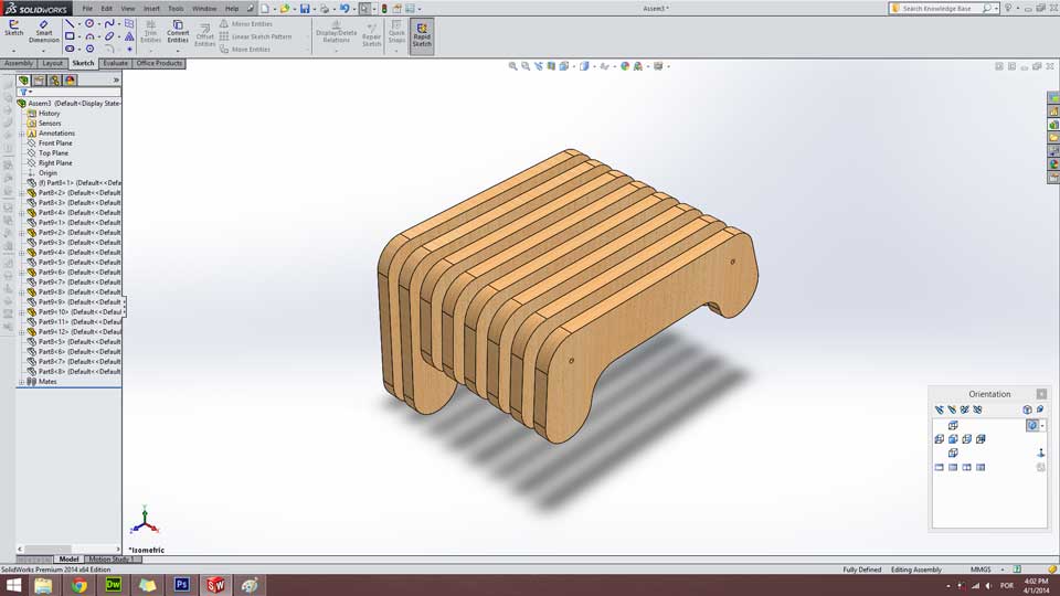
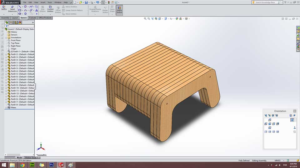
I used Solidworks to make all the parts and assembly. As I said it is based on the same lines of the Layer Chair but bearing in mind it's a stool and the proportions have to change drastically. Wanting to maintain the same language troughout the all project and having the need for a center piece, I sketched this one:
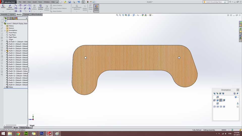
So, the stool is composed of many layers that are glued to each other and get pierced by two threaded rods to hold position and provide some flexibility
The next image illustrates the assembly process and the other one th product assembled.
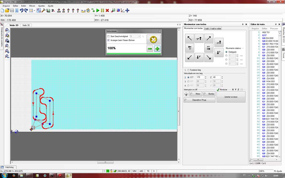
The Ouplan
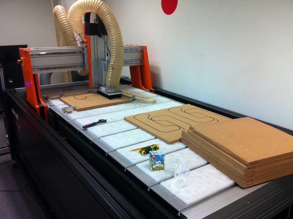
This is the equivalent of a ShopBot, but it is made by a portuguese company. Ouplan specializes in the making of CNC routers of different dimensions. The one we have here at Fab Lab EDP is the small version, but still pretty large to work with. It has a total work space of 1900mm by 900mm. Comparing to the Modela, it is like the big cousin where you can mill big things instead of small ones, but never with the same precision as the Modela. Here is a picture of it:
So, first of all you need to have your project's files in DXF in order to import them to the Ouplan. You are going to work with a new software called Aspire. In Aspire you can prepare the toolpaths for your work to export them to the Ouplan software. Open the your project's first file you are going to work with in Aspire. At this point you'll have something like this in your screen:
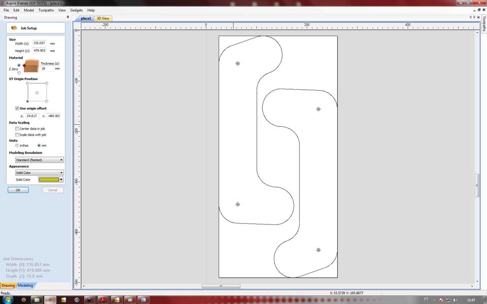
Hopefully you will get a different picture than I (laughs). After opening your DXF in Aspire you'll need to configure some settings. First define the size of the board you are going to cut. Then you can input it's thickness and and set the origin point. Don't forget to reset the X and Y values for the origin offset so the machine recognizes the zero point.
After this you're going to create your toolpaths for the CNC router. Configure everything accordingly to your previous settings and then save them.
The basics of setting the zero point in the machine are pretty much the same as the Modela. What I mean is that regarding the first stages of the milling process, there's always a need to define the zero point and the start height of the end mill. After pinning your material to the machine you have to define the zero point where it will start milling.
Define the board dimensions and define the zero point. After everything is all setup, it's time to start milling your parts.
Final Output
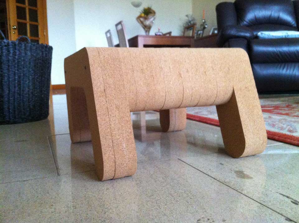
All parts glued together and left with clamps all night. I also used M6 threaded rods in order to align all the parts while gluing them and to give more flexibility and rigidity to the structure.
Project Files
In order not to overload my page, I didn't place my files here for download, but if you need the stool files ask me for them and I'll be pleased to send them to you.
If you need them you can download them here at these Google Drive links:
Thak you all for your time! See you again soon!