Week 12: Output Devices
Since I didn't have the time to complete this assignment when the time was right, I decided to combine next week's assignment, network and communications, with output devices. So, the PCB you will see here is a mix between those two subjects.
Among all the possible outputs we could choose, I made up my mind on the RGB LED because my final project will involve this type of LED. Since my final project is based on a concept that a underwater vehicle (jellyfish like) moved by shape memory wire, I thought it would be an excellent idea if the temperature that affects the SMW could be visualizes trough the color changing on the RGB LED. This way it would be possible to know if the voltage supply applied to the SMW is going as smoothly as possible.
Eagle Lands!
I must admit that I know myself and my interest in learning new softwares, but I didn't think that I would get really used to Eagle and would get to like it so much. Add components, wire, and label them. Change to board view and route them all together, and a few minutes later:
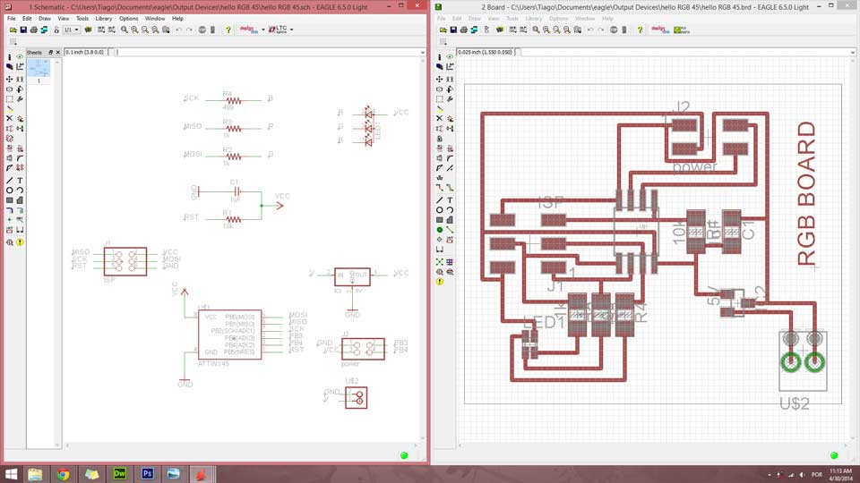
The difference between the original RGB LED board and the node board (besides the RGB LED) is that there are two extra connections in J2 header for power, one that connects Tx to PB3 in the ATtiny45 and another one that connects Rx to PB4 in the microcontroller. This way I was able to combine both board designs, taking the components from the RGB LED board and connecting the necessary dots to make ir work as a node board as well. This was extra helpful because I saved a lot of time in the design and fabrication.
Here you can download my schematics and board files to work with them:
Program the Board
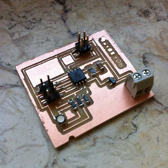
After some battles with the multimeter and the power supply, I managed to be able to program my board and flash the RGB LED. At first, something was not right because I was using a 5V battery, but then I remebered that with those 5V, the voltage regulator would not let the power flow trough the ciruit, so I had to change it to a 12V power supply in order to program the board. After that I was able to successfully change those 12V to a 9V battery, and light up the LED. This is the result:
Project Files
You can download the Eagle files for this project right here:
Thank you for watching everyone! Stay tuned.