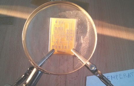
This assignment is all about sensors. The main objective is to understand how do the sensors function and to think about their useful application.
My final project includes two sensors that will measure the temperature and humidity of humans body.
BEFORE YOU START. CHECK THE TUTORIAL FOR SOLDERING
 |
This assignment is all about sensors. The main objective is to understand how do the sensors function and to think about their useful application. My final project includes two sensors that will measure the temperature and humidity of humans body. |
You can find the schematic`s example on the fab academy page |
To make the temperature sensor, we need: 1) Four resistance of 10K 2) A capacitor 3) A header 4) A sensor 5) ATTINY45 6) FTDI Draw your circuit in Eagle program. Search for all the elements in the fab library. Make sure, that there are not any double line of the "net". Give names for all the pins and connections. Label them. More information in my tutorial "how to make the circuits in eagle".
|
 |
|
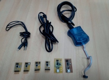 |
When we`ve got all the sensors done, we are to program it. Use AVR to verify if yours boards are funcioning (if they give a green light).
|
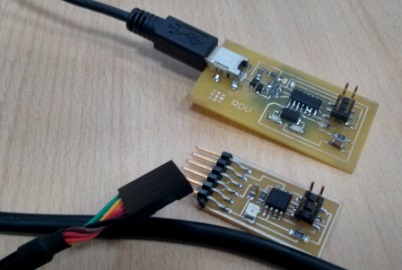 |
Then connect the ISP board with computer and with your sensor. |
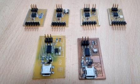 |
Here we have one temperature sensor, one optical (phototransistor) sensor, one txrx (output, input), one button sensor and two ISP. |
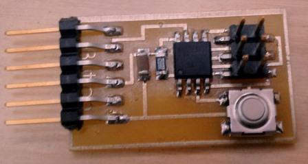 |
consists of: ATTINY45; a button; a capacitor; FTDI; header; and the resistance of 10K. |
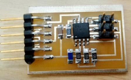 |
Its also the temperature sensor that detects the decreasing temperature |
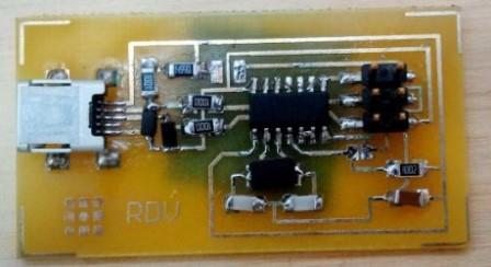 |
This is the ISP - a board that we use to program all the inputs and outputs |
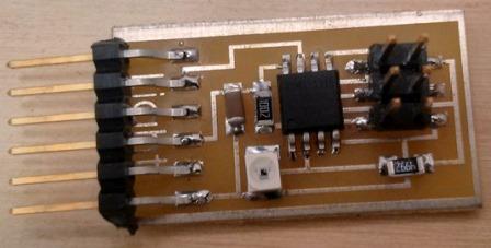 |
The phototransistor. Detects the differencies of the light. |
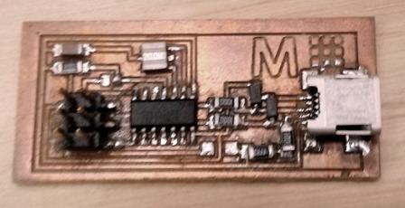 |
This is anothe ISP. The first one did not function. |
THE PROGRAMMING PART WATCH THE VIDEO! LOAD BOARD AND TEMPERATURE BOARD PROGRAMMING |
 |
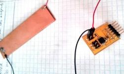 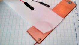 |
To program the TXRX or the load board use the ISP, FTDI cable and the usb cable. |
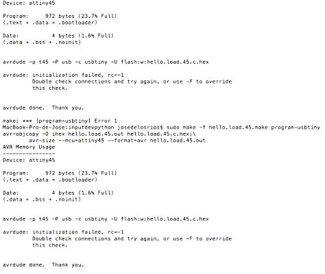 |
Load Error |
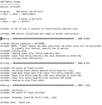 |
Load fuses OK |
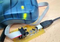 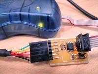 |
Here you can see how we can detect that the board is well-soldered and can proceed to the programming part. |
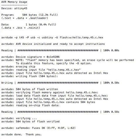 |
Temperature´s sensor fuses OK |
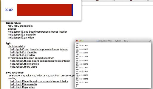 |
Temperature board python code |