The topic of the week is the fabacademy network : we must make a network connection between two microcontrollers.
I will try, starting with the example "serial asynchronous" to do a minimalist network with optical fiber that gave us a member of the lab.
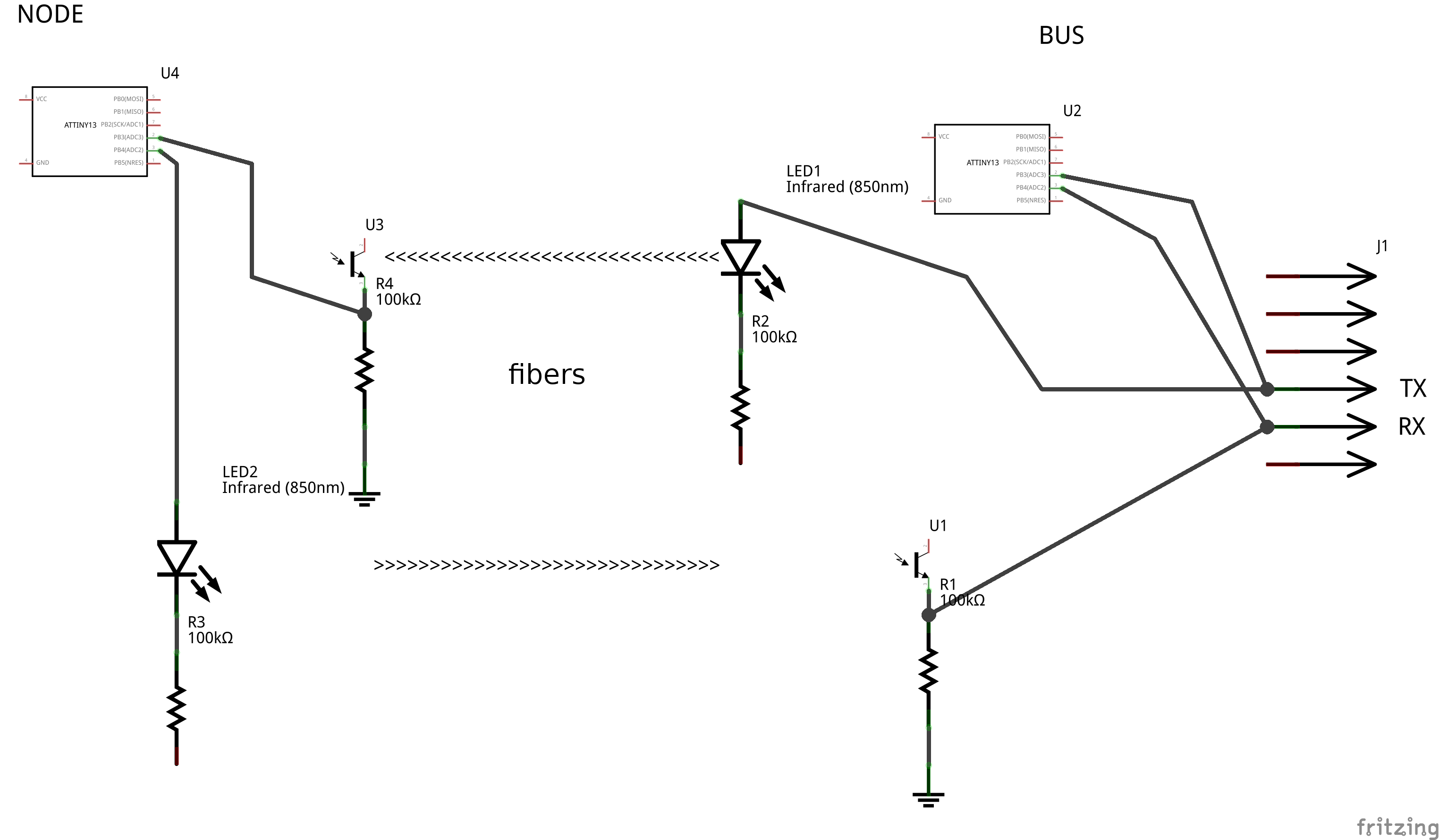
In other words, transform RX and TX signals from the serial link light signals using an infrared LED and a photoresistor.
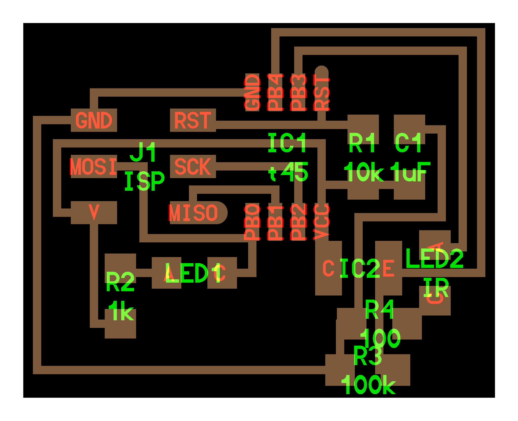
I'll take most of the serial communication circuit, but replacing the electrical connections by
As I have yet prism to send and receive in the same fiber. I'll fix two fibers (one go, an another for return)
WARNING there is no diode controller input!
if you plug the PSU upside down, it burns!
I combine holes and cut to do the mill in the same operation
from the basic serial example, serial communications are simply optically replicated using the LED and the photoresistor.
I would resume code serial communication (by inverting the inputs and outputs of the node)
is the node connected to the computer with an FTDI connection
it is the remote node.
For the moment, the state, the network is not expandable because nodes should replicate the signal for the following, with another pair of LED / phototransistor.
For this first test, I did a dialogue between only two units.
After the first milled circuit when cutting, plate moved because I had used a tape of poor quality.
To catch the error, I made a slightly wider cut to avoid damaging the circuit in case of misalignment.
The result is a little less pretty, but functional.
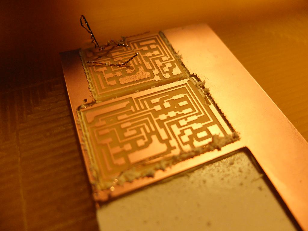
I am now more comfortable with CMS soldering
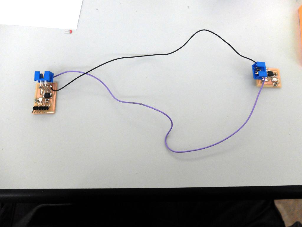
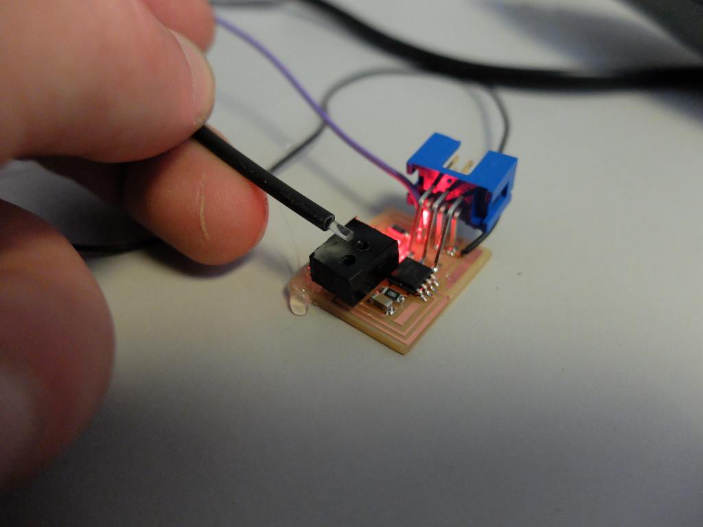
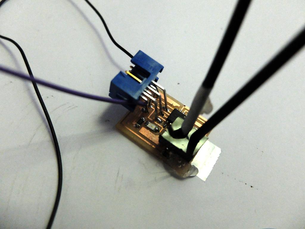
I forgot the power for the node : it's why I've soldered this mirific wires ;)
For the fiber, I build smalls connectors, made of black plexyglass, attached with hot glue.
I just picked up the code the serial example .
identical to the bridge I inverted inputs and outputs to the node
The bridge does not respond as I would have liked: when I send "0" in the terminal, the LED lights up but stays on, and I have no message in return.
I suppose that the components I added to the line of communication trouble the transit.
But the node responds quasi as expected :
it's weird because I indexed the node to "1": I guess the response time of the phototransistor is not there for nothing, "rise and fall time = 15US"
in the code bit_delay_time = 100us
A mesure with an oscilloscope confirm this (here for a "5" message):

in green : the serial signal
in yellow : the optical signal recieved by the node
It's stange because the reaction time of the optical chain is very longuer than the 15uS indicated in the datasheet.
Or the led add a reaction time, or the poor quality of the fiber made
the light signal less bright, that causes a longuer reaction time from
the phototransistor...