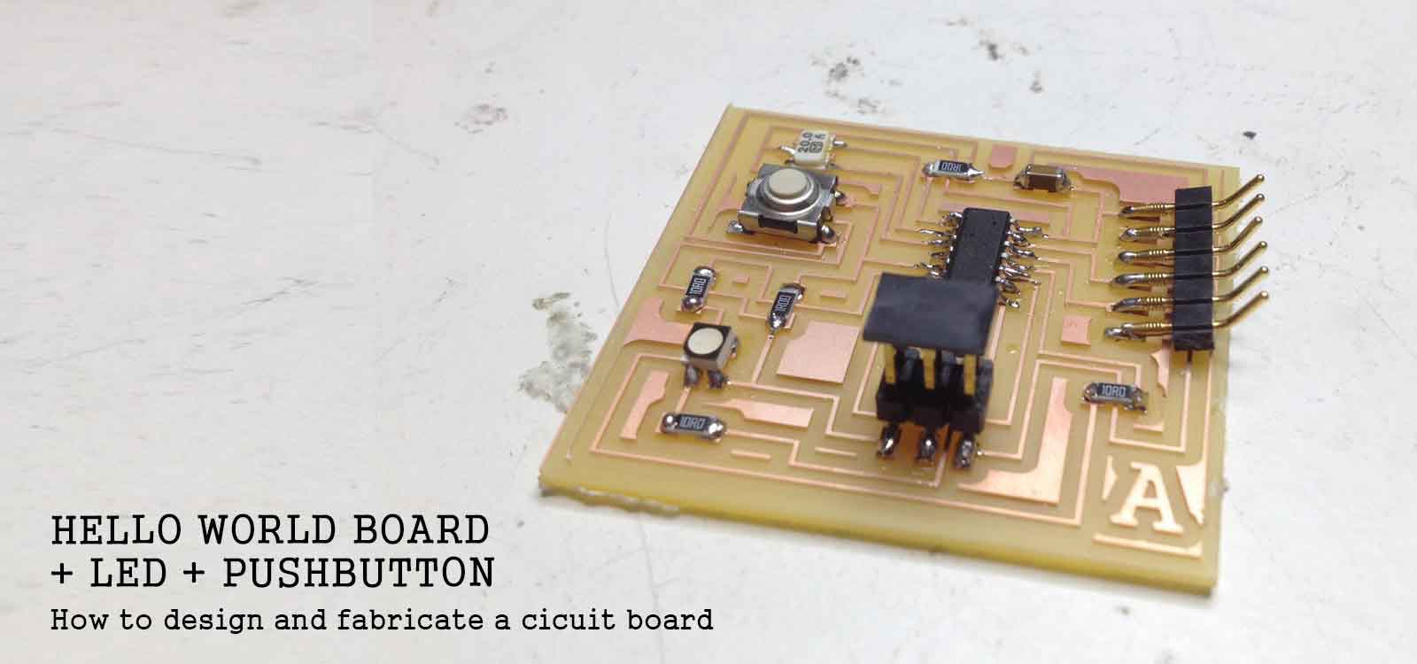
This assignment was about understanding the basics of electronics design. We had to replicate a Hello Board and add at least one button and LED. We used Eagle (Easily Applicable Graphical Layout Editor) for creating the circuit boards, as well as the Adafruit, Eagle and Fab Academy libraries for getting the components we needed. To begin I watched and followed the first 3 CadSoft Eagle Tutorials by Jeremy Blum.
Download the files here:
Eagle Schematic [.sch]
Eagle board [.brd]
1 CAP1206 capacitor
1 Crystal Resonator
1 ATTINY44-SSU Microprocessor
5 1206 Resistors
1 6mm Switch (push button)
1 ARDUINO_SERIAL_PROGRAMSMD Pin
1 AVRISPSMD Pin
1 LED RGB LEDRGBOLD
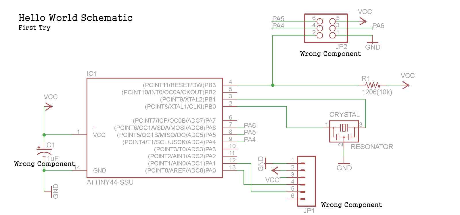
I felt pretty comfortable using the interphase of Eagle. However, the first complication I had, was finding the correct components in the libraries. For example: I had to change the capacitor since I had chose a polarized one. Once I had all the components on my Schematic Design I began to make the connections
I followed the hello.ftdi.44 .png file to start connecting the components, but I found difficult to understand how the resistors and capacitors work. I had a look at the Encyclopedia of Electronic Components by Charles Platt, to get a better understanding of how I could use them on my board, specially when trying to add other new components.
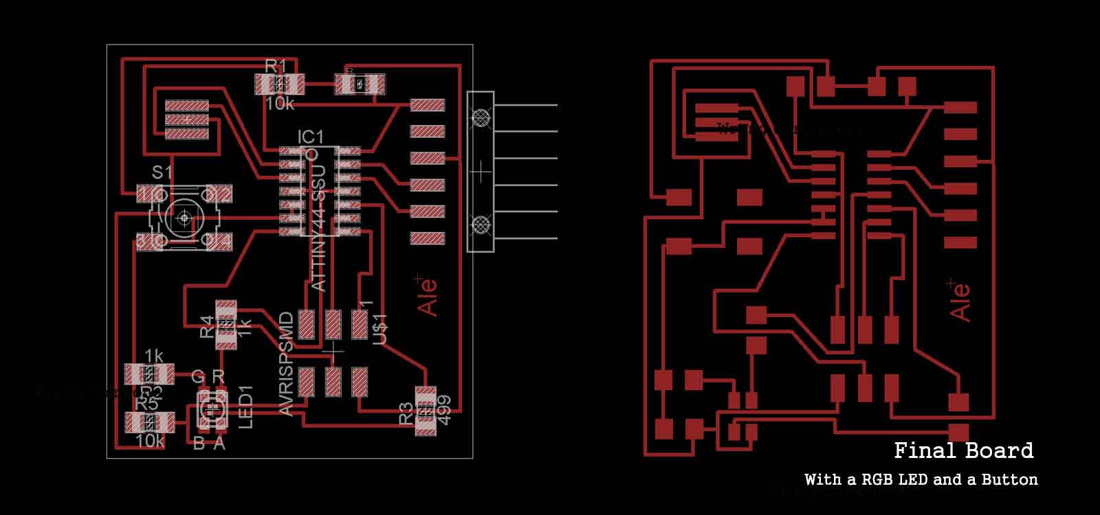
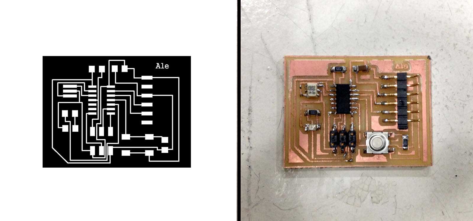
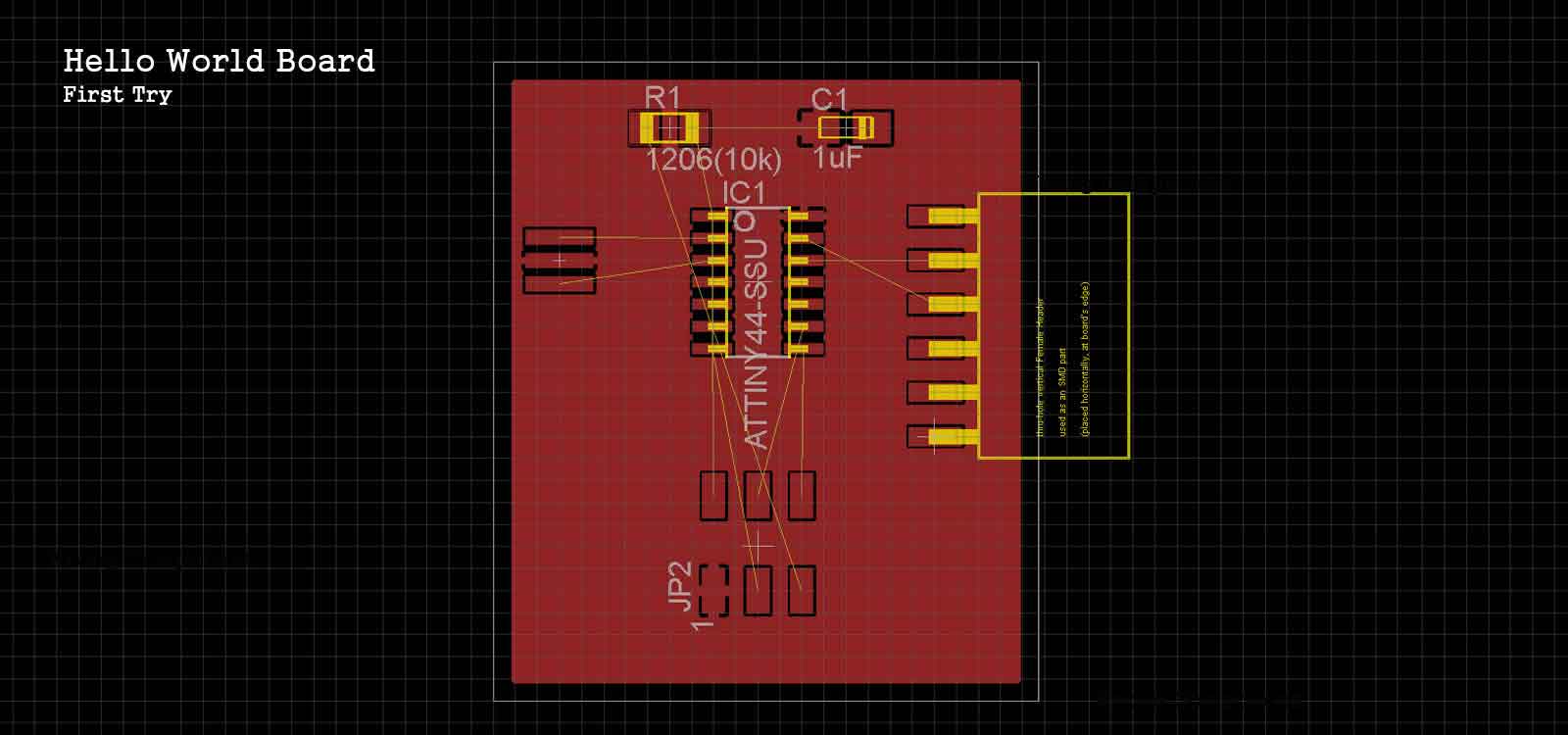
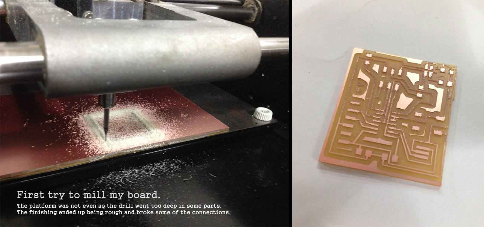
I decided to add a push button and a RGB LEDto the board. To calculate the resistors I checked the technical sheets of the components and used an Online Resistor Calculator. When I finished the Schematic, I continued with the creation of the Board. I moved the components around the best way I could and ran the autorouter. It gave me a very good set of connections and I just had to manually change a few. When the file was ready on Eagle, I saved it as an .png, made the contour in photoshop and sent it to the Roland Modela Milling Machine to fabricate the board. I tried several times. The first try didn't come out I as expected because the platform of the machine was uneven which made the drill go too deep in some parts, giving the connections a rough finishing.
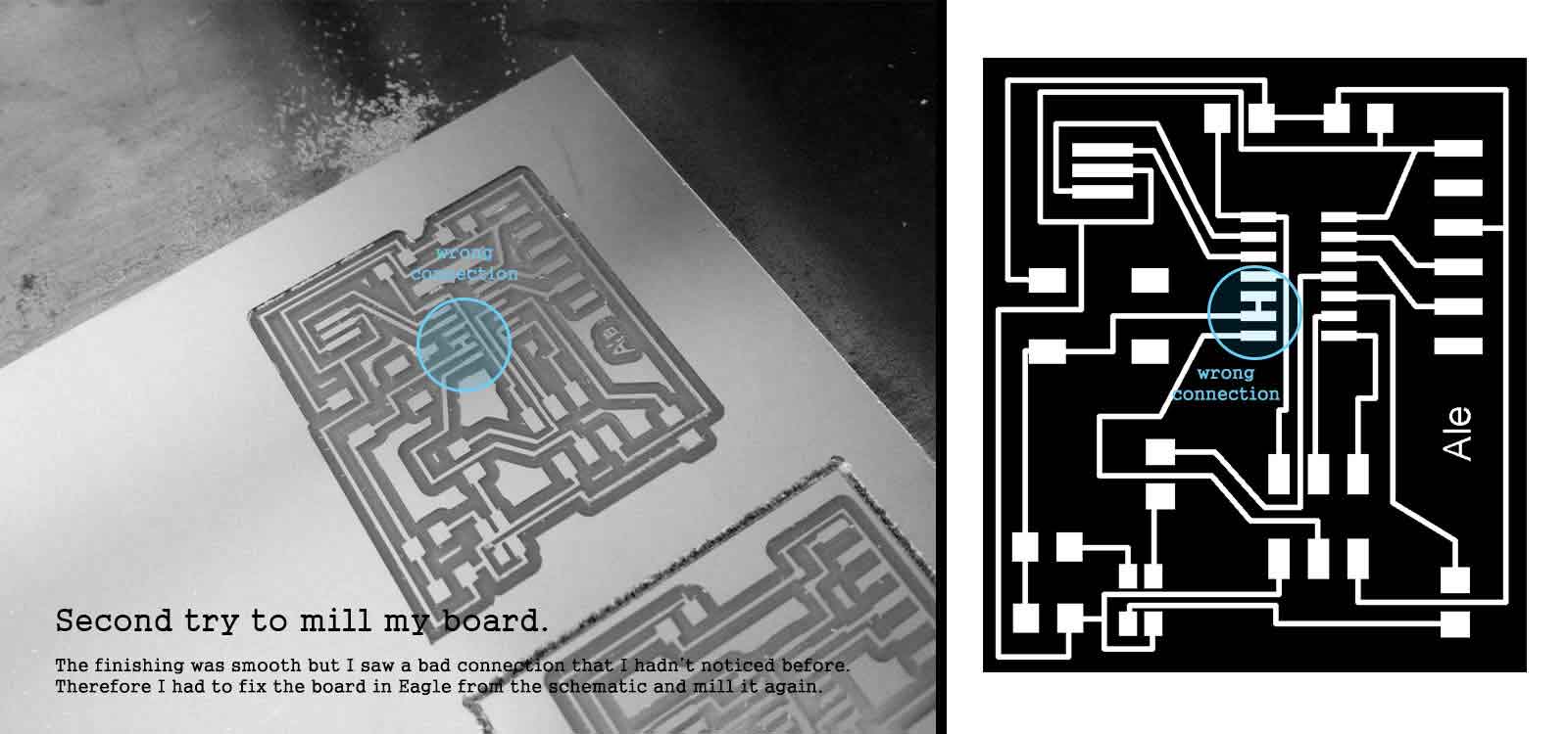
The second try came out clean and very well defined, but once I started welding the components, I noticed a mistake: two of the pins of the microprocessor were connected for some reason. I had to go back to the Eagle file and check it again. The problem was that I had given the same name to both pins by mistake. I fixed it and sent it to the milling machine again.
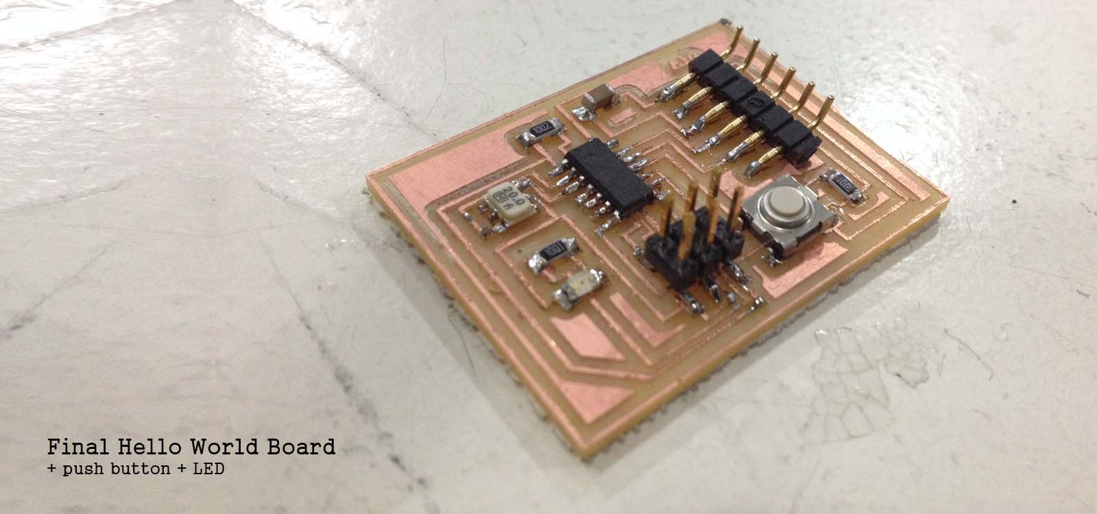
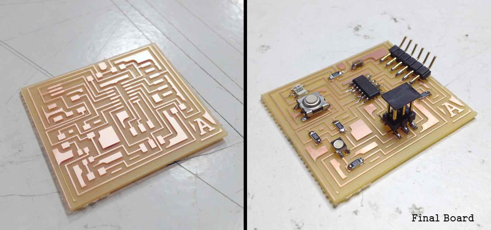
The third try worked out. I sent the file and it worked perfectly and soldered the components.
NOTE:
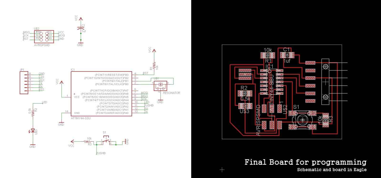
When I reached Week #9: Embedded Programming, I realized that this board doesn't work. There is a bad connection. With a little more understanding of circuits, I re-designed it to be able to program it. At the end I managed to make a way smaller and simplier board. Here it is: