The project started at the beginning of the semester as a Ludic Tool for kids in developing countries to learn electronics and programming by creating little robots of recycling materials. As I started learning about these subjects, I realized that this idea was way too complicated for a short-term final project. Therefore, I brought it down to a smaller scale but trying to keep the same concept.
The FrankensToy is an interactive module that allows kids to play with electronics and create small robots with day-to-day items. It is a ludic toy for learning about about electronics and prototype little systems or machines using things they find at home.
FabAcademy2014: FrankensToy in process [ working! ] from Alejandra Diaz de Leon on Vimeo.
1. What does it do?
2. The design [ 2D Drawing and 3D modeling in Rhino ]
3. The body [ 3D printing in nylon ]
4. The connectors [ 3D printing in PLA and Laser Cutting ]
5. The selector [ Laser cutting and Coper circuit with the vynil cutter ]
6. The activator [ Laser cutting and 3D printing ]
7. The brain [ Electronics: Attiny44 ]
8. How does it work? [ Programming: Arduino IDE ]
9. License
10. Files
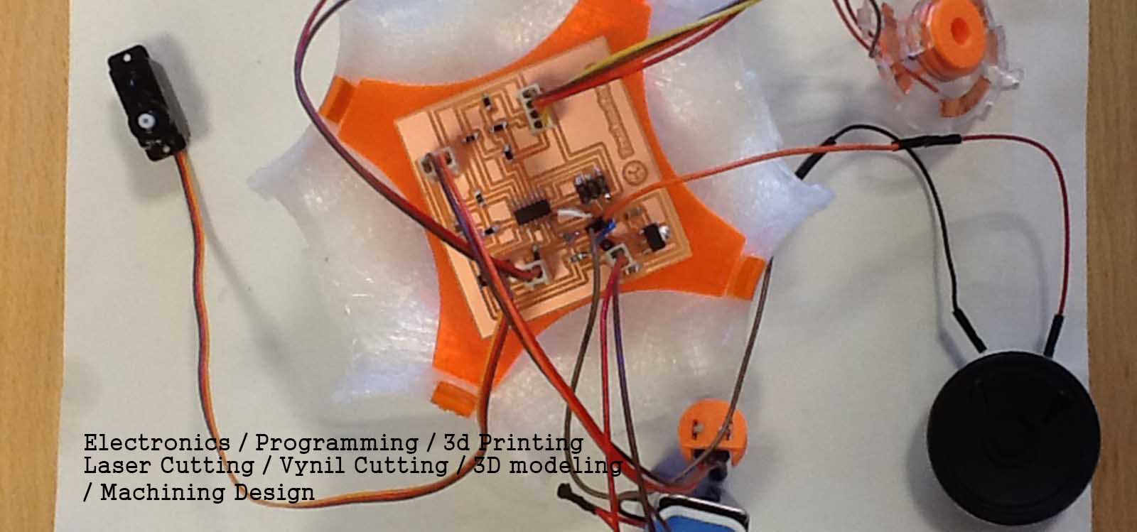
This module has 3 inputs and 3 outputs that allow interactivity among the kids, recycling items and the toy itself to create little machines. Each module contains the following:
*One activator (input activated by conductive materials like paper clips, a metal fork, etc)
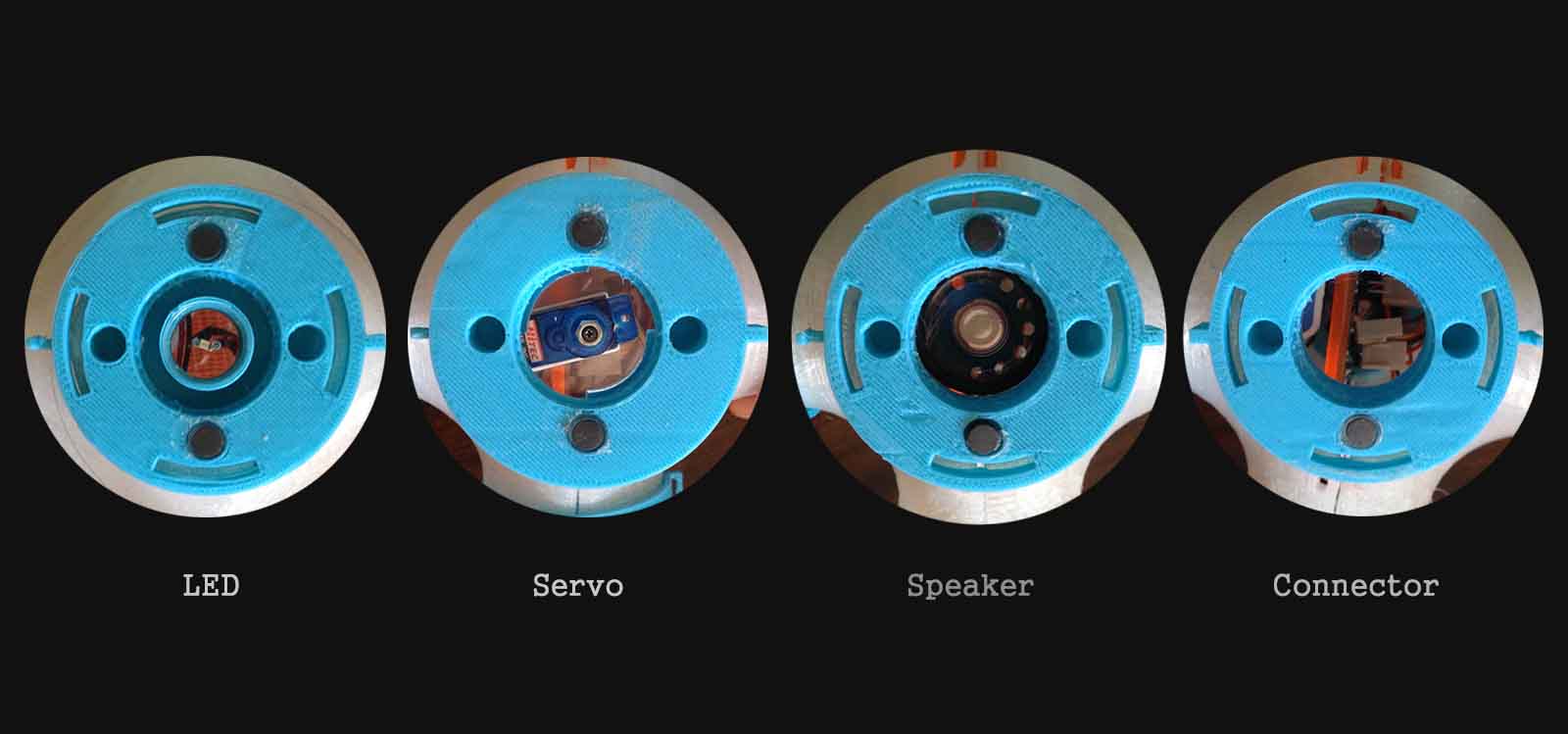
*Three different outputs (speaker, LED and servomotor)
*One selector (designed by me) for choosing one or two of the three outputs to make the robots interactive.
*One potentiometer to control the behavior of the outputs (speed of the servo, sound and brightness of the LED)
*Connectors that attach recycling materials such as plastic bottles, cans, cardboard boxes among many others, as well as other modules to create the FrankensToy.
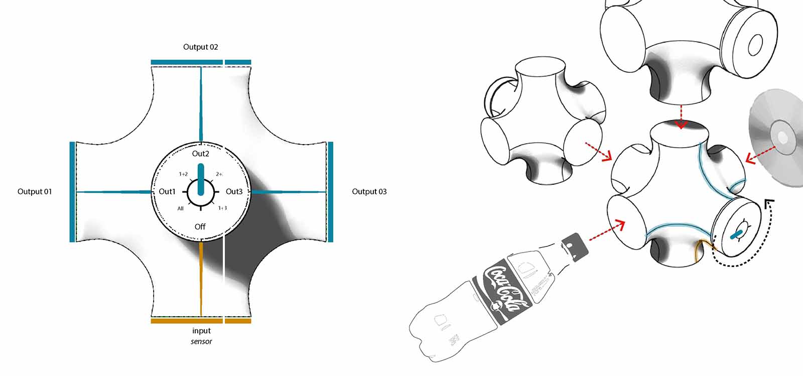
When I began designing the module, I only knew the basic idea of what I wanted to do. At the begining I chose to have a small geometric (8x8cm) shape wit 4 to 6 faces. Each face will have each input and output. Then, I realized that each face had to be de-attached from each other in order to give more "freedom to the connectors that will attach the recycling items. Therefore, I designed a more organic shape with 6 faces. For 3D modeling I used Rhinoceros. This was the most complicated shape to draw, so I will tell about the process. I made the model like this:
a. Draw a cube
b. Draw a circle in each of its 6 sides
c. Using the command _arc join the tangents of the circles with curves
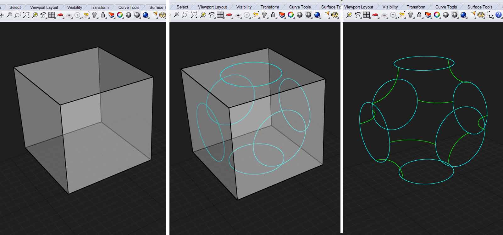
d. Using the command _split split the curves to make a network of curves.
e. Using the command _patch create a surface with the curves you drew before.
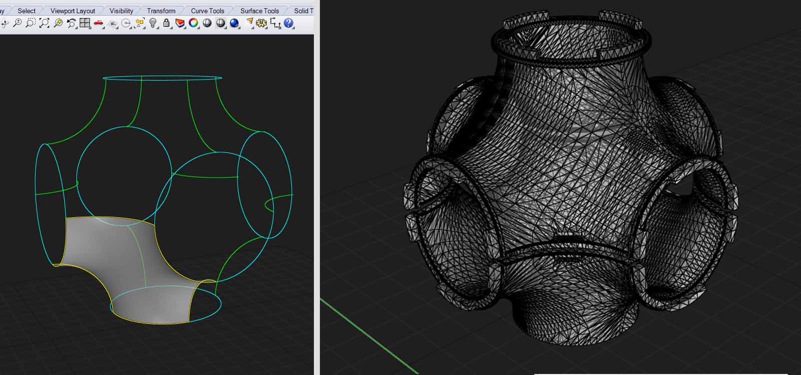
f. Rotate (and copy) this shape to have the final one.
g. For a better resolution for 3D printing, smooth surface by trimming its sides and loft the edges
h. Convert it into a mesh for have it ready for 3D printing
I ended up having a 11x11cm organic shape which brings me to my first lessons learnt:
Lesson 01 Before 3D modeling make sure of which components you will use because they will define the shape and size of your project.
The body of the FrankensToy was important to design because it holds the rest of the parts of the module. Because of the shape, the best way to make it was 3D printing it. I had to make a lot of tests to have a decent final piece.
Lesson 02 Design and Model thinking it will be 3D printed.
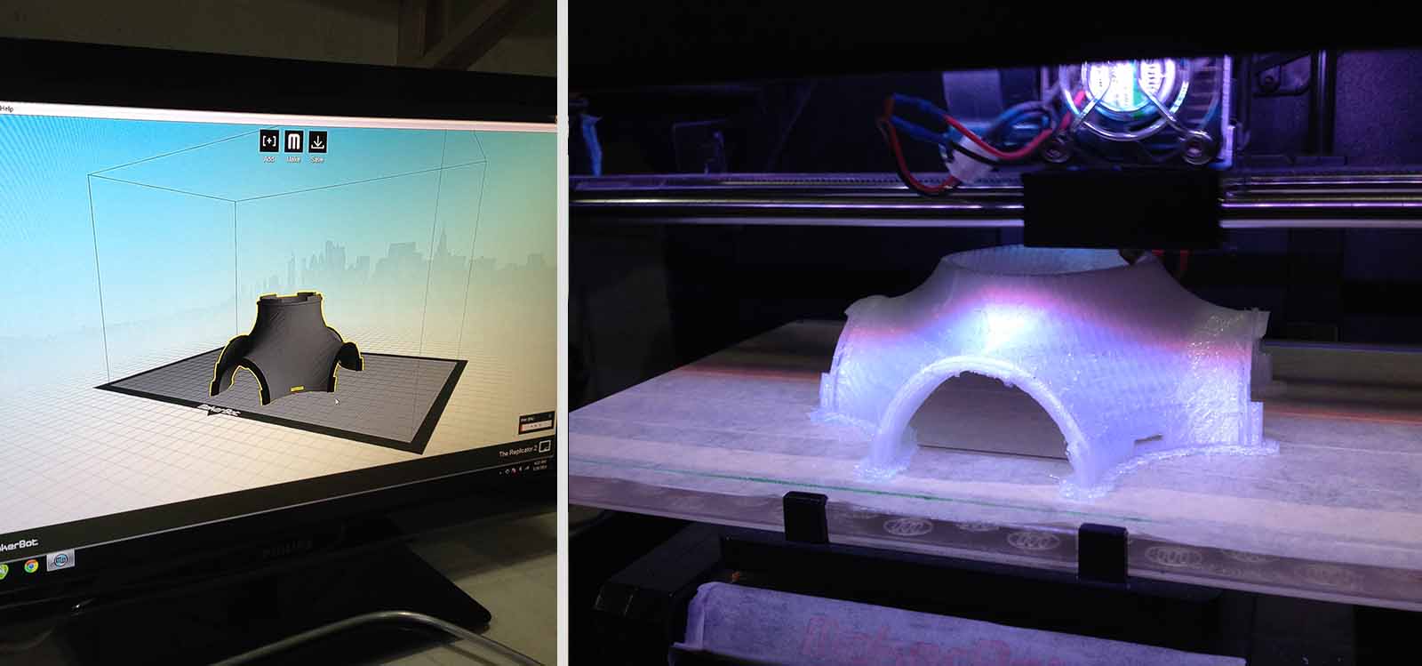
I already had the 3D mesh from Rhino but the first step to 3D print is to prepare the .stl file. The first time I sent the file in the Makerbot 2 some parts didn't print and it was because I had a polysurface hidden under the mesh. I also needed to test the infill and resolution of the piece according to the material and finishing I wanted. It was also important to check if the other parts that I Laser-cut and 3D printed where gonna press-fit properly. And finally, I had to cut the geometry in two parts to print it separetely because the angle of it was too steep if Printed from bottom to top.
For this process I used the Makerbot 2 with the following settings: 1.75mm Nylon filament: 30% infill, 15mm layers, 245 degrees, with Raft . Each part took 4 hours.
Recommendations for preparing the .stl file
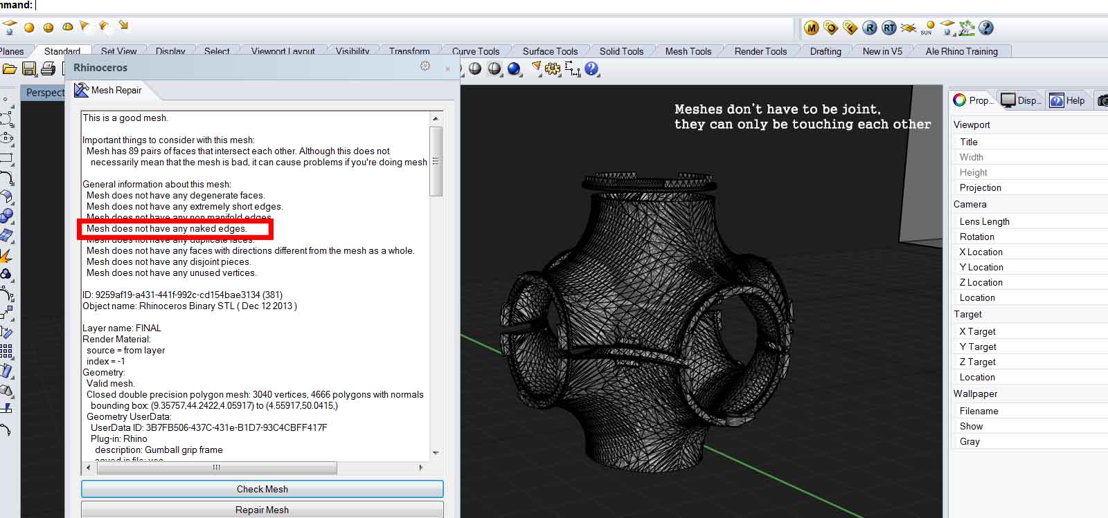
a. In rhino check if the mesh is good. You can have some errors but the only one that matters is naked edges. Type _meshrepair and make sure there are no naked edges. If there are some, it's probable because there are open edges. Close them and do it again until it's clean.
b. Check that it’s in millimeters
c. Don’t let polysurfaces or any other objects in the file! It won’t print.
d. Type “show” to make sure you don’t have any hidden object, turn all the layers on, and type SelDup to make sure you don’t have something duplicated.
SOMETHING GOOD I LEARNT You can change the filament while printing! You just have to pause it and find the option in the printer.
Recommendations for 3D printing
a. Design and Model thinking it will be 3D printed
b. Don’t leave steep angles of more than 30-45 degrees.
c. Tolerance: It you are gonna press-fit, leave 1mm loose.
d. Tiny pieces are not precise on the Makerbot or Replicator. Better to laser cut or cast.
e. Work with Surfaces, lines and polysurfaces. Do not ever work with meshes unless it’s necessary.
f. Think of how it will be print. Add small supports (don’t let the machine do it)
g. Design one thing, test it, redesign, redraw, do small tests before printing everything!
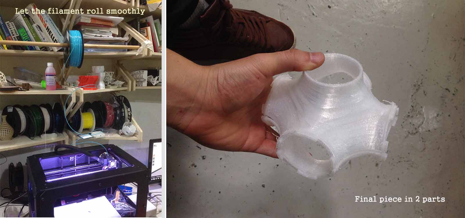
h. Don’t let the filament too tight because it can pull the extruder. Always have enough of it loose or on something that lets it roll smoothly.
The connectors of the FrankensToy have two functions: they attach other modules as well as the recycling materials to the module and the also contain the outputs. Therefore they had to press-fit perfectly in the 3D printed body.
For designing them, I made a little research of what were the most common items mexican children could find at home, looking at the things in the Basic Goods Basket.
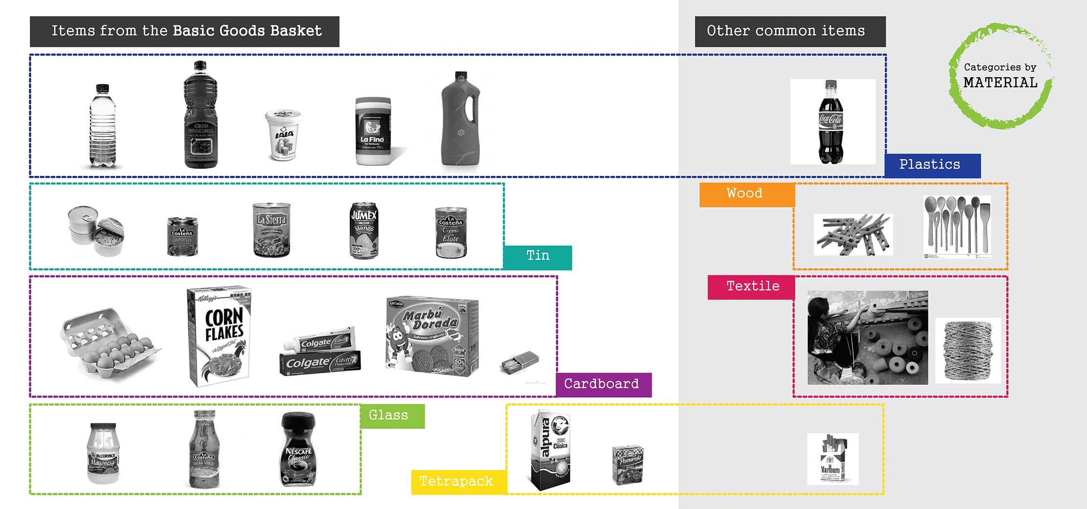
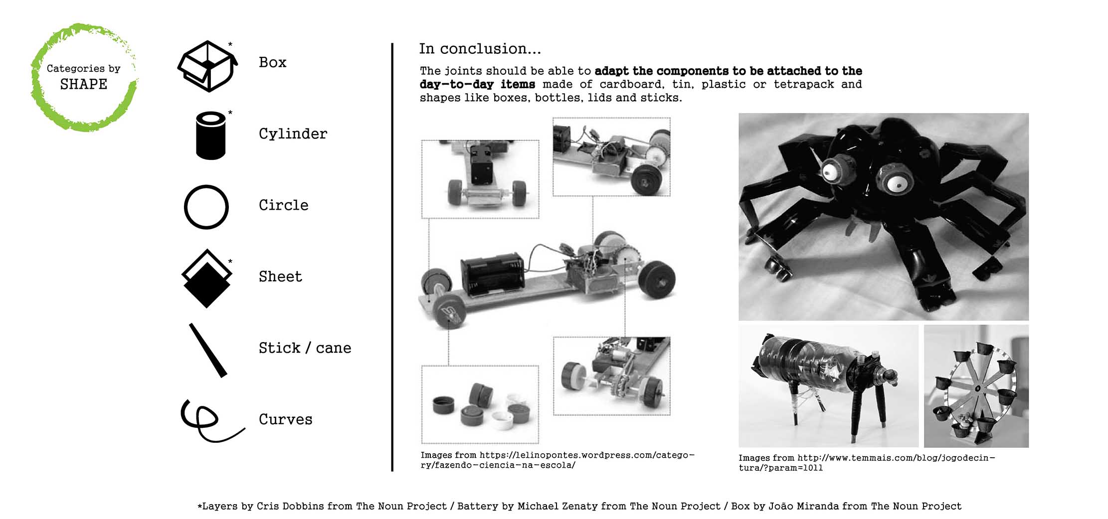
Knowing this, I designed an connector that could attach these elements and other bigger things, and that would fit in the body.

Each one of this components also has one output (LED, servo or speaker). The main part of the components was 3D printed but it also has Laser cut and vynil cut parts.
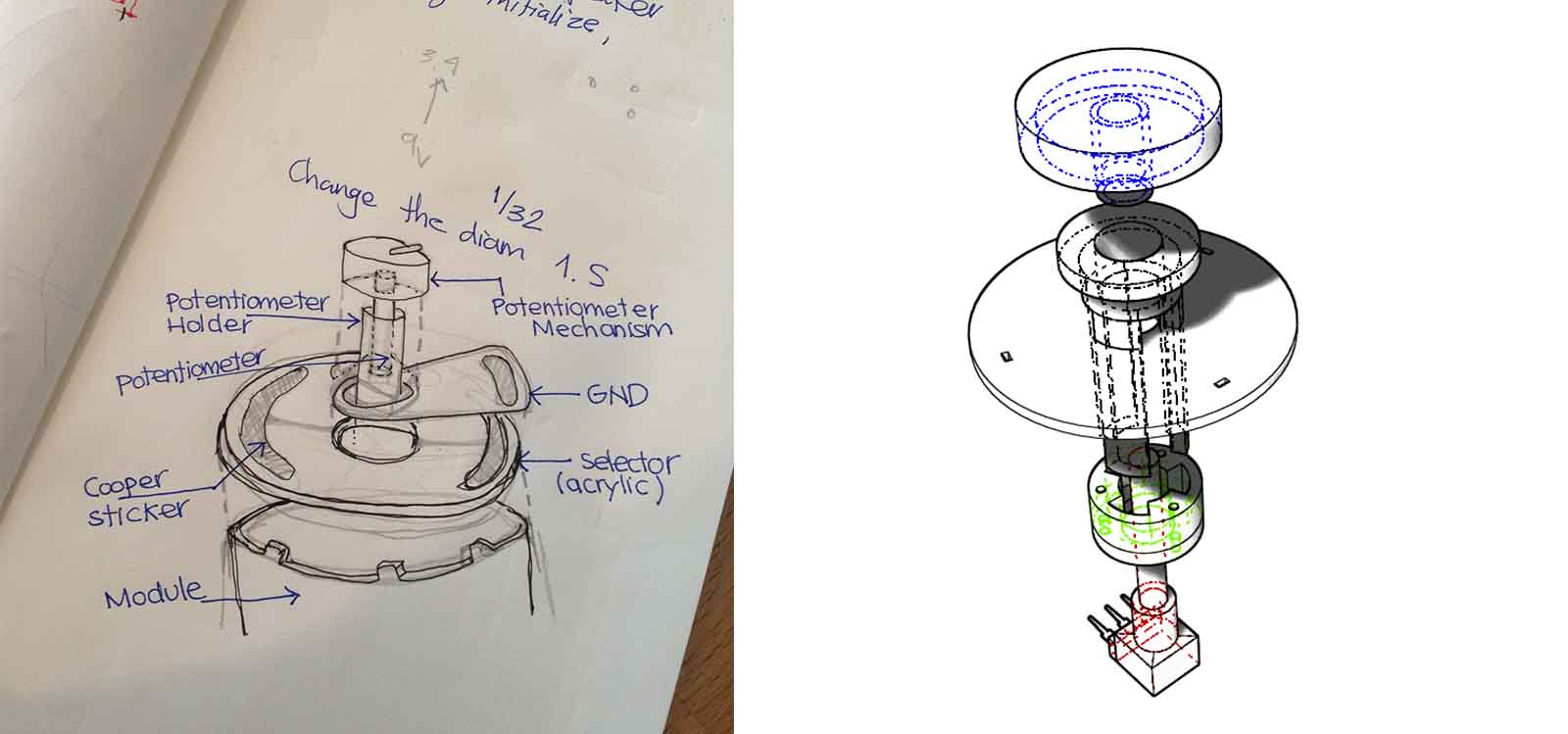
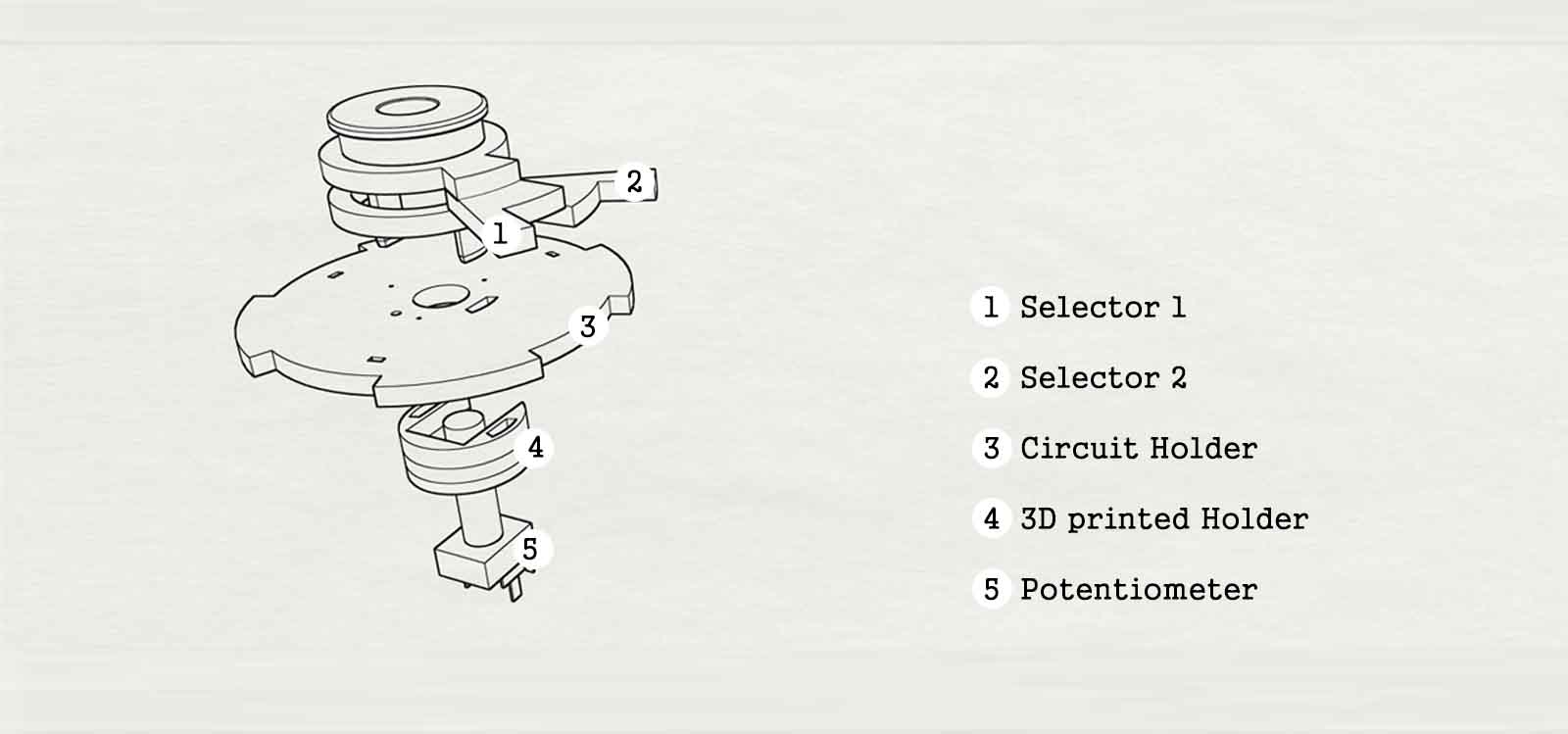
The selector is a 3 position switch fabricated for fitting the design of the FrankensToy. It allows the kid to chose which one of the outputs to activate. He can play with one or two at the same time. It is made of 3mm transparent acrylic with the circuit made with coper paper cut in the vynil cutter. It was very important to test the parts that needed to fit perfectly, before cutting them all.
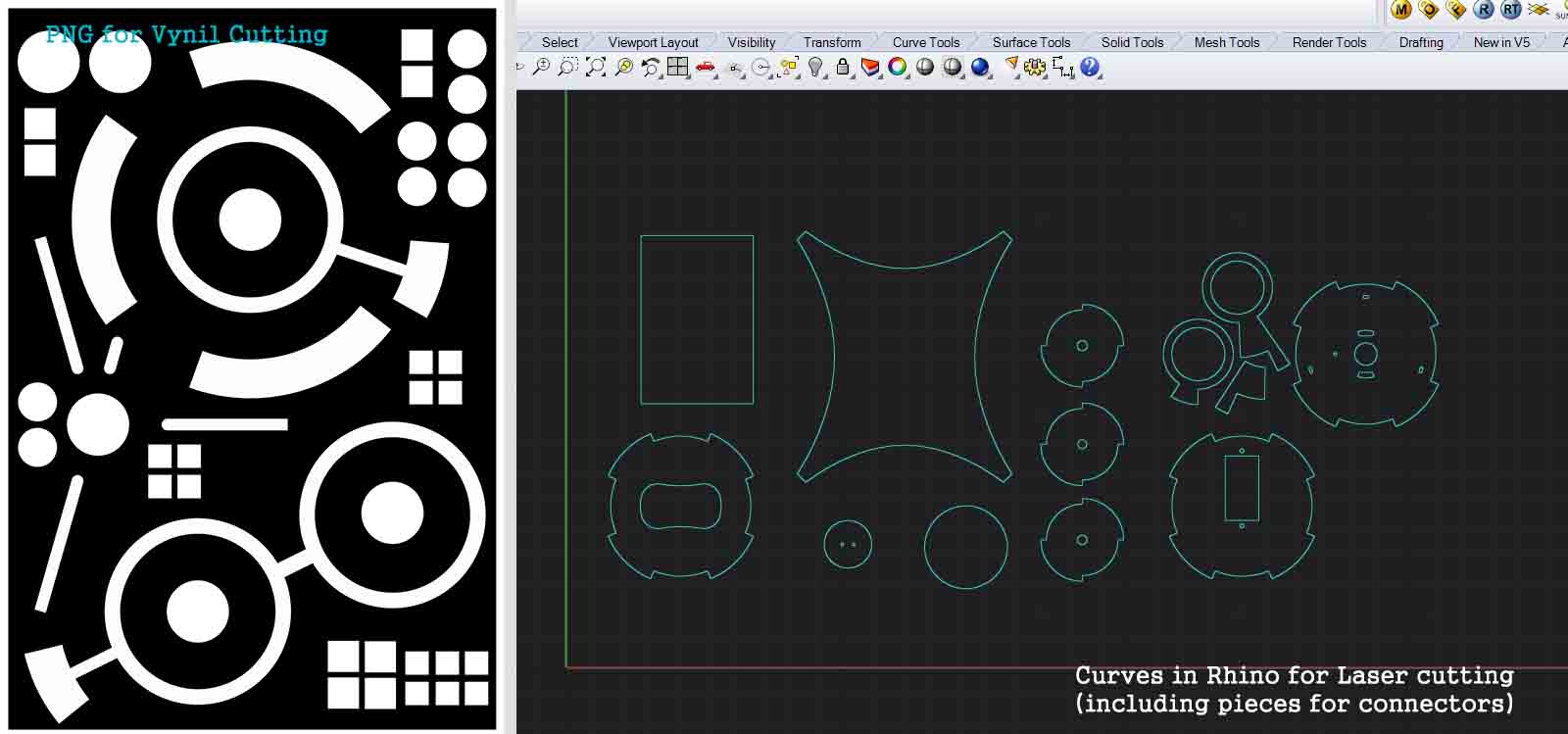
I got the lines for laser-cut from the Rhino 3D model, just by using the comand _dupedge of the parts I needed. After testing these cuts, I modified the curves and gave them -0.5mm of tolerance so they could press-fit well.
For laser-cutting this, I got the settings from the Wiki Fab Lab Barcelona webpage, and the setting i used are these: Transparent Poly(methyl methacrylate)(3mm) / Plexiglass,Speed: 15%, Power: 60% . As for the coper, i obtained the curves to cut from rhino 2D and exported them into illustrator to make a PNG. Then, I sent it from fab modules to the Roland Vynil Cutter.
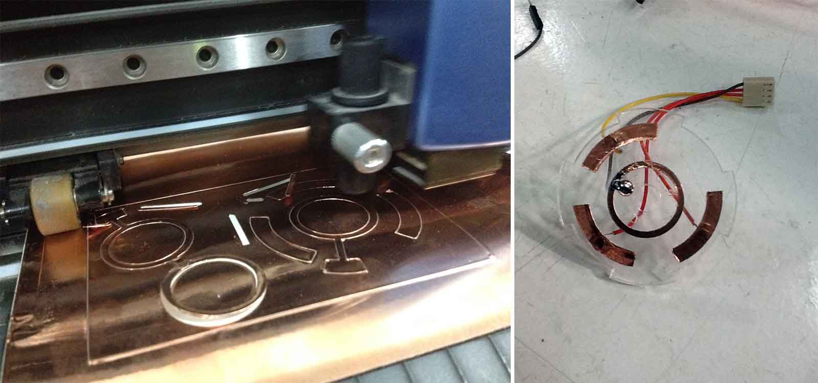
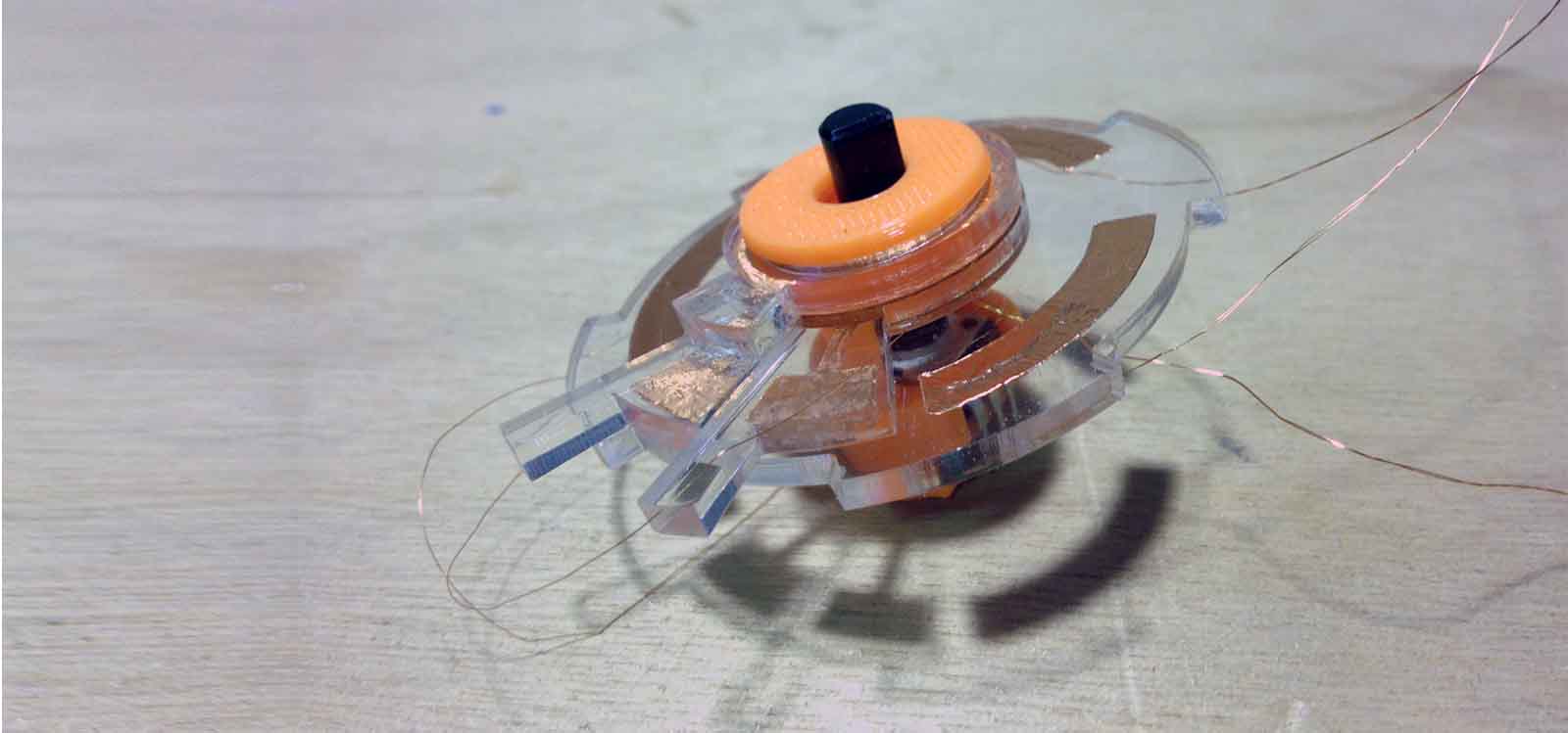
In the middle of the selector, there is also a potentiometer that works independent from the selector. The piece that holds them together was 3D printed in PLA. I finally assembled everything together and soldered the wired to it. I tested it to make sure the coper sticker made contact and it did!
Here is a video of the selector working properly:
FabAcademy2014: Selector Working from Alejandra Diaz de Leon on Vimeo.
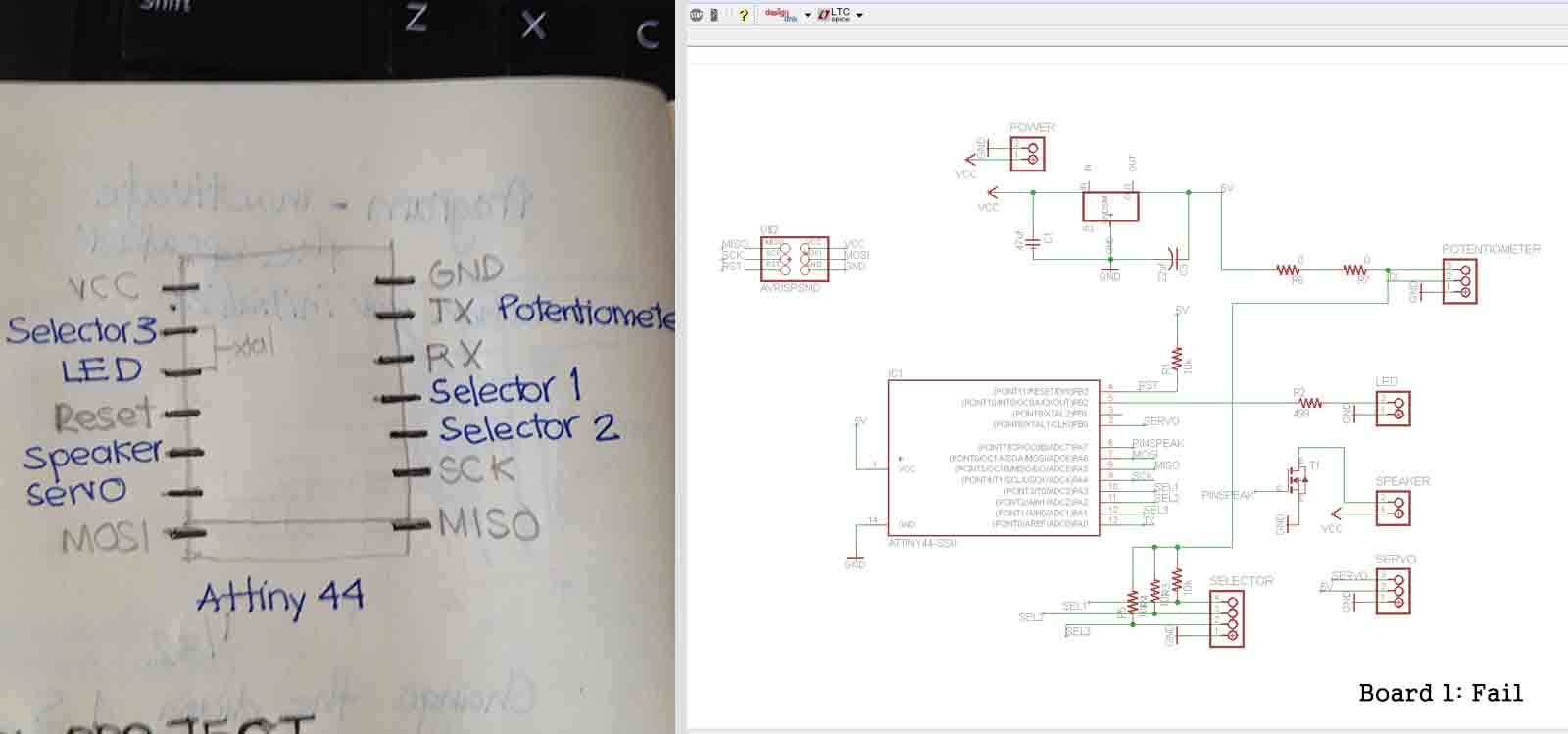
I started thinking I needed a fabduino to connect each board from each output to it. I talked to Luciano and he recommended to have everything in only fabduino since I was just developing one module for the presentation. When started designing the board in eagle I realized it maybe had too many pins that I was not gonna use. Then I talked to Francisco Sánchez and Andrew Leek from Fab Lab Sitges and they recommended to use the Attiny44 . I removed the cristal to get the pins I needed so I didn’t have to reuse the MISO, MOSI and SCK.
I designed the first board like this:
Recommendation for making boards in Eagle: Andy Leek gave me some tips of how to make the board in eagle in the best and fastes way possible. Here are the steps:
a. Spare all the components so you can see clearly how they connect.
b. Arrange them in the most logical and clean way possible. Use theRatnestoption
c. Connect all the grounds first.
d. Connect all the VCCs
e. Connect the rest
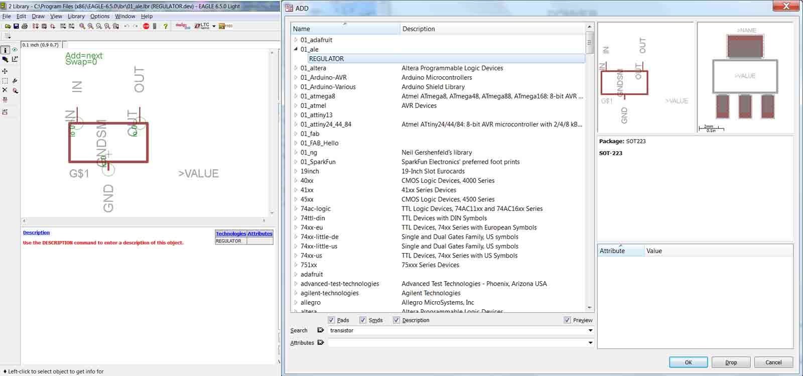
Even though these tips helped me a lot to save time, I had to add two bridges to finish it. Also, since I was gonna power the module with a 9v battery, I added a 5v regulator and had to make my own component in eagle and add it to my library to understand better how it connects. To make a new library in Eagle, have a look at this Instructable tutorial.
Here are the schematic and board images of the first board I made:
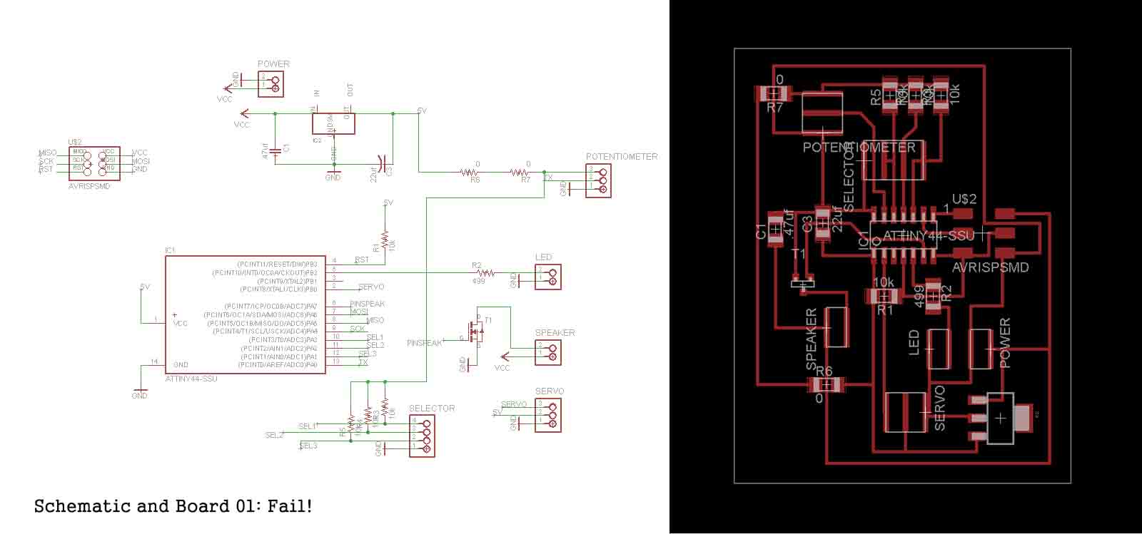
This board didn't work. Even thoughthe AVR did recognize it, I couldn't make anything work. At this point, I had 1 week before the final presentation, so I decided to go to Fab Lab Sitges and finish my project there. Francisco Sánchez was very helpful and supporting. He recommended to check one component by one [ Lesson 05 ], so I removed most of them and started testing them. Iused a simple Arduino example to check it the potentiometer and LED were working and properly connected. I succeeded, but then it all got complicated. When I added the selector, I noticed I had made lots of mistakes in my board. Here I explain my process:
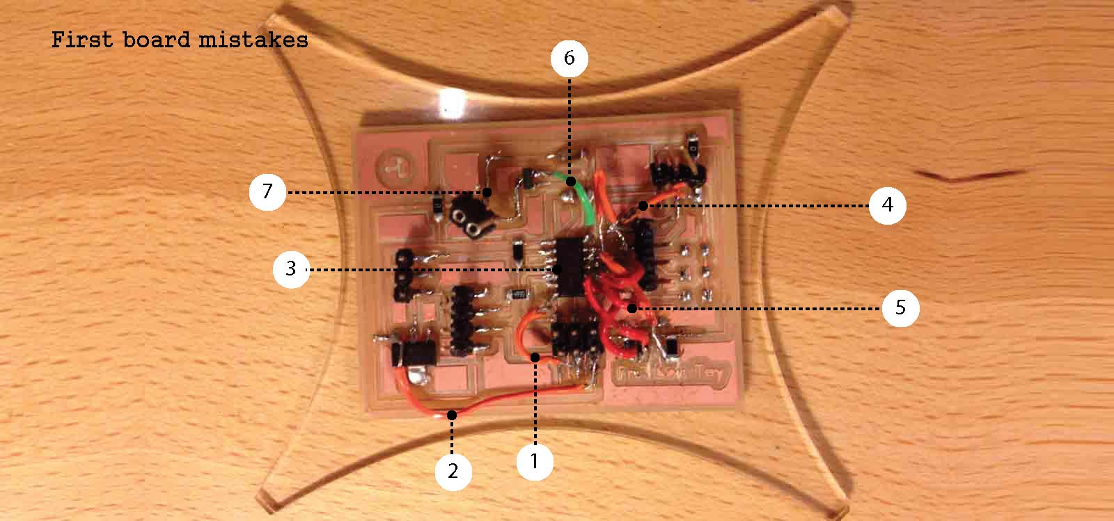
Mistakes of first board:
1. The first I did was checking that all the components were well soldered. Then I checked that they were connected to the right things and here I found a mistake. By mistake when doing the board in Eagle, I overlapped the connection between MOSI and RESET in the 6 pin header. So I cut the connection and added my first bridge.
2. I had the VCC of the 6 pin header connected straight to the 9v battery, instead of from the 5v that come out from the regulator. This burnt my attiny44 so I had to change it.
3. I forgot to add the 10 uf capacitor for the Attiny.
4. I connected the selector to pins and GND instead of VCC. Explanation in following point.
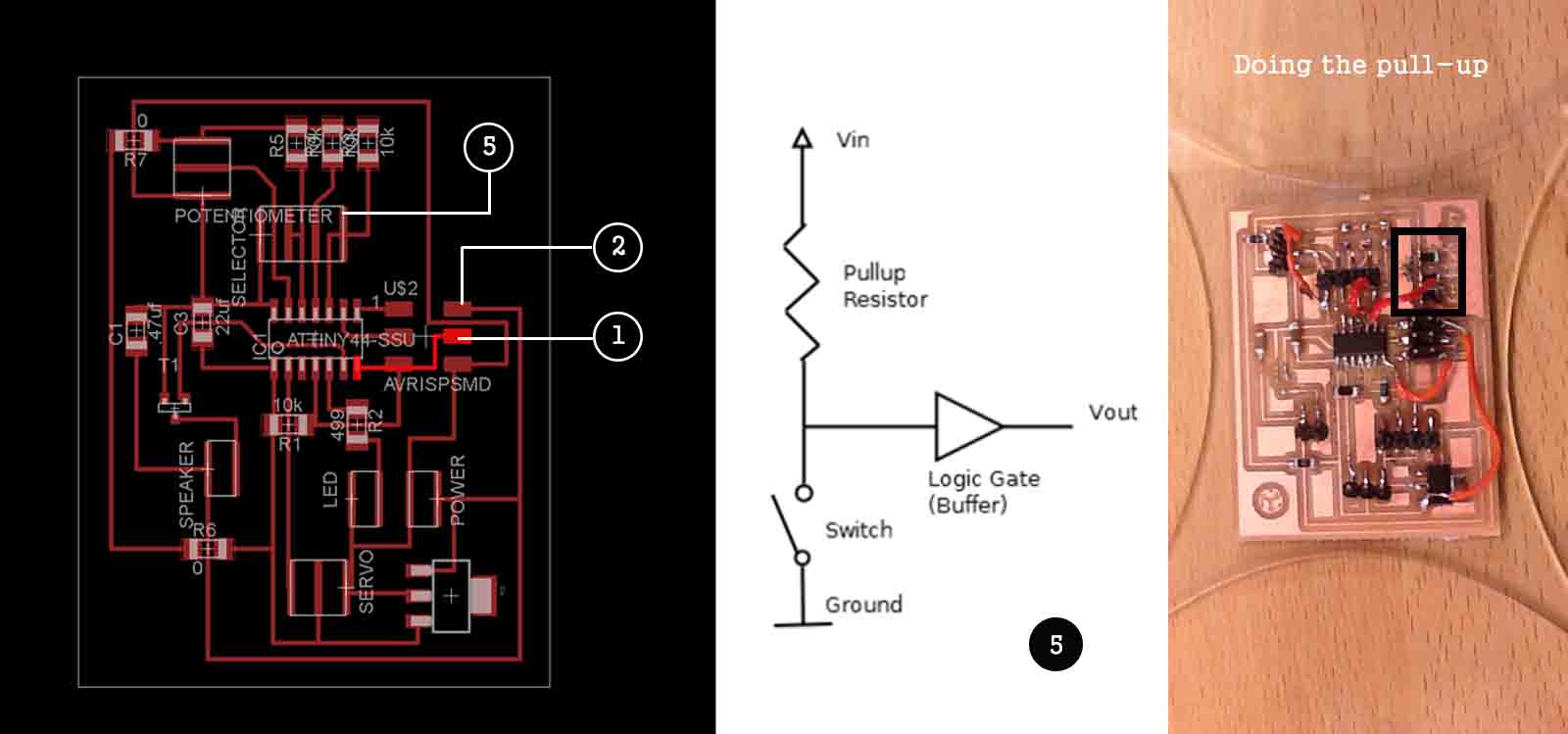
5. The logics of how my selector worked were wrong. I had just connected 3 pins of the attiny to the 3 pins of the selector and added un 10k resistor between them. Then I connected the other pin to Ground. Which brings me to Lesson 06 : every switch has to be set with its pull-up resistors (see image attached below). After fixing this for each pin, my board looked crazy.
6. I couldn't make the mosfet for the speaker work, so I had to connect it in a different way, skipping the amplifier and wire it straignt to the pin with a resistor.
7. After doing all this, my board look like a real Frankenstein. I pulled the wires of the speaker and the coper came out with it. I tried to fix it but I didn't succed so I had to start over.
I remade the board. I fixed all the mistakes in eagle and milled the board again. I tried one more time to make the mosfet work because without it, the sound of the speaker was very low. I realized that the connections were correct but I was using the wrong component. The right one is the MOSFET N-CH . Now everything is working properly.
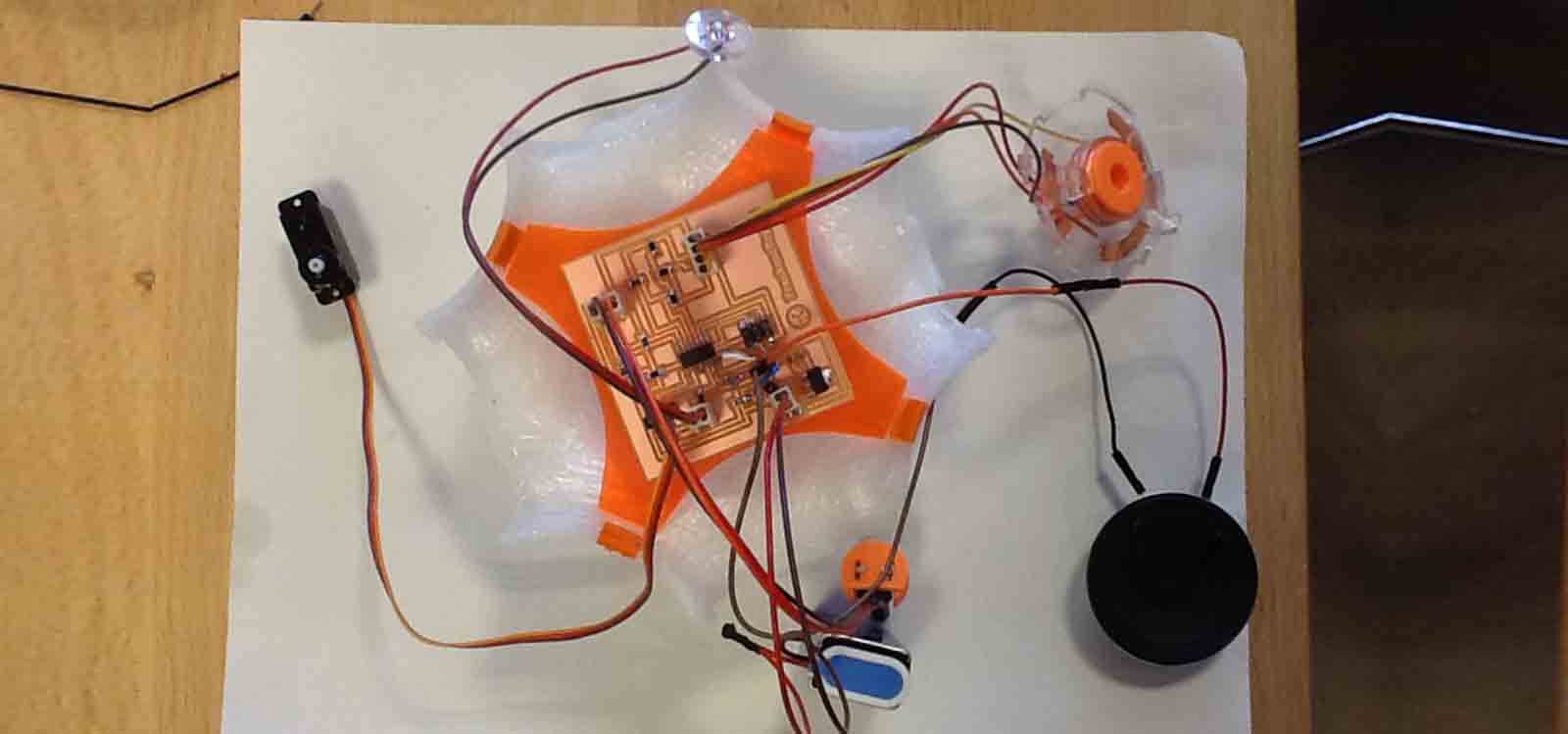
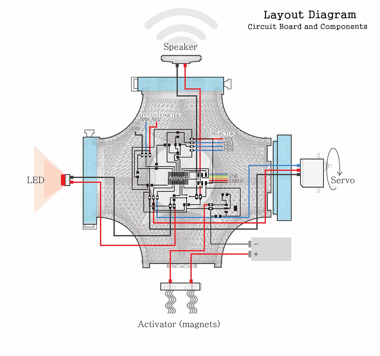
Here is a Layout Diagram that explains the circuit and its components:
Once all the electronics were correct, I needed to write a code to compile all that I had tested before. Since I am new in programming, I used the Arduino IDE. It was not very complicated to make it work, but I wasted a lot of time and got very frustrated trying to use the libraries. So, Lesson 07 : The speaker.h and servo.h library do not run in Attinys.
I found out that the old softwareServo.h library works on Attinys and tried to use it. However, it is no enough just to drop it in the library file. Lesson 08 :To install the library, you need to create a new folder under the Libraries folder in the Arduino program location and drop the SoftwareServo.h and SoftwareServo.cpp file you downloaded here .
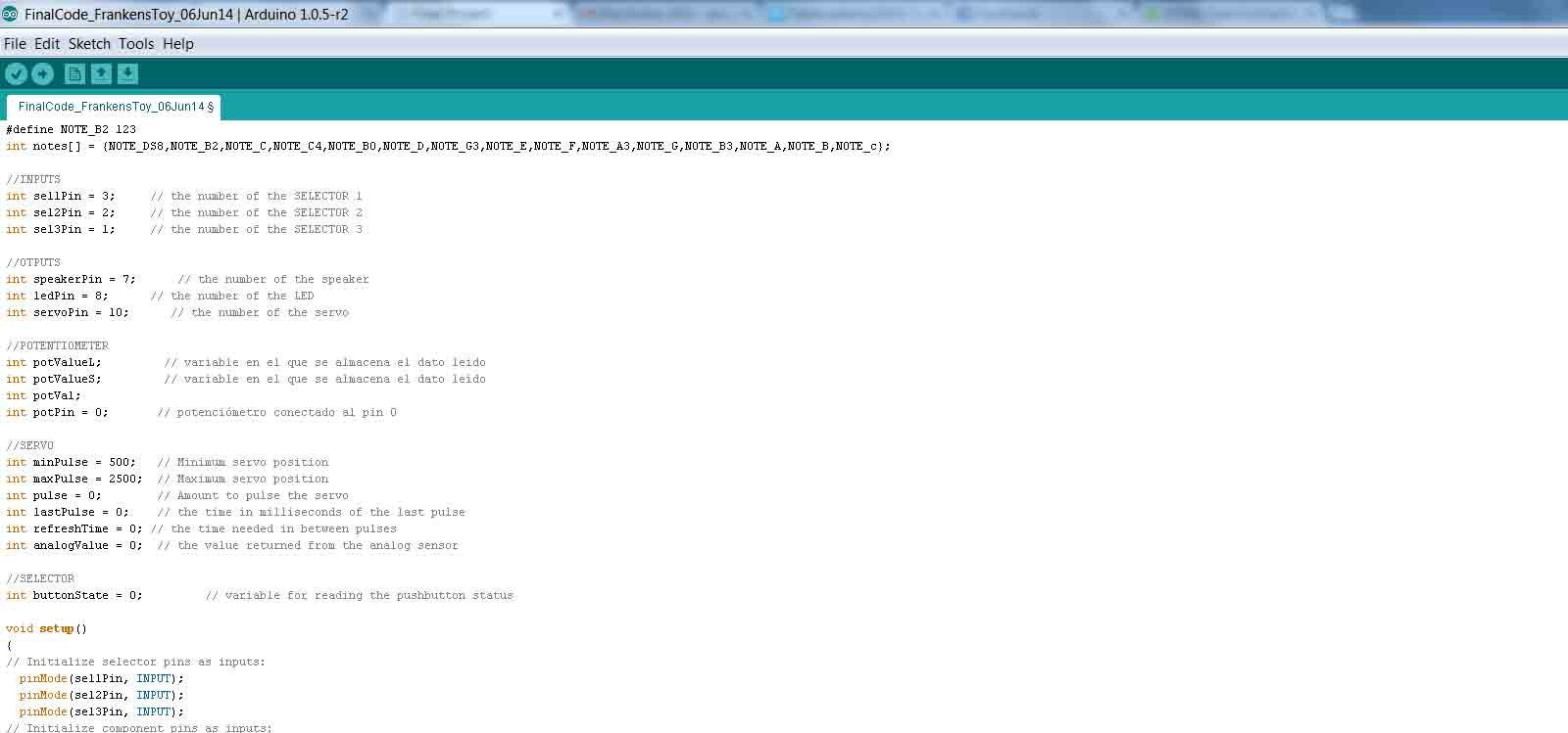
At the end, I decided not to use libraries and the code looks like this (you can find the code file in Arduino IDE at the end of this section):
The FrankensToy is an Open Source Hardware and Software licensed under MIT license.
The License Terms go like this:
Copyright (C) [2014] [copyright holders]
Permission is hereby granted, free of charge, to any person obtaining a copy of this software and associated documentation files (the "Software"), to deal in the Software without restriction, including without limitation the rights to use, copy, modify, merge, publish, distribute, sublicense, and/or sell copies of the Software, and to permit persons to whom the Software is furnished to do so, subject to the following conditions:
The above copyright notice and this permission notice shall be included in all copies or substantial portions of the Software.
THE SOFTWARE IS PROVIDED "AS IS", WITHOUT WARRANTY OF ANY KIND, EXPRESS OR IMPLIED, INCLUDING BUT NOT LIMITED TO THE WARRANTIES OF MERCHANTABILITY, FITNESS FOR A PARTICULAR PURPOSE AND NONINFRINGEMENT. IN NO EVENT SHALL THE AUTHORS OR COPYRIGHT HOLDERS BE LIABLE FOR ANY CLAIM, DAMAGES OR OTHER LIABILITY, WHETHER IN AN ACTION OF CONTRACT, TORT OR OTHERWISE, ARISING FROM, OUT OF OR IN CONNECTION WITH THE SOFTWARE OR THE USE OR OTHER DEALINGS IN THE SOFTWARE.
The reason why I consider this the bet option, is because it seems like the best deal. First, I can share the project and allow any person to use it, improve it and share it again (after all, most of the development of the FrankensToy is based in other people's work who have shared their ideas online). Also, it makes clear that the use of this information is a responsability of whoever uses it. I think this is important to point out because, altough it could be helpful for some, it is also not a finished product and it can have small errors or could cause an accident if misused.
.STL file for 3D printing:
1. Body
2. Clips
3. Speaker/Connector
4. LED/Connector
5. Servo/Connector
5. Activator
.DWG file for Laser Cutting
1. Connectors, selector and activator
.PNG file for Coper Sticker Cutting
1. Selector Circuit
Eagle files
1. Schematic
2. Board
.PNG for milling boards
1. Traces
2. Holes and cutting
