>> Week 18, May 28: Project development
Complete your final project, tracking your progress
Spiral development
Round 1:
After brainstorming, I choose an idea for my final project
 |
Round 2:
I identified the modules that would be part of the project. And I started to search the information in order to document about the operation and particular technical details.
 |
Round 3:
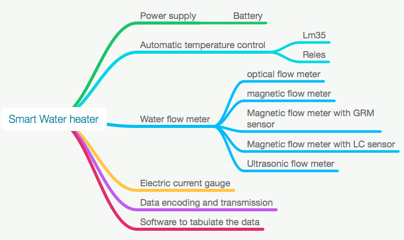
I reviewed the work schedule (date of delivery for final project) and considering the collected data and my knowledge, I defined the modules that will be part of the first prototype (Power supply and Automatic temperature control). Below, you can see a block diagram of the circuits that will be part of the prototype. Finally, I prepared a schedule for manufacturing of the first prototype.
|


Round 4:
After identifying the electronic circuits I would use in the project, I made a simulation of the electronic circuits: temperature controller, temperature monitoring and setting, synchronization signals generator and feeding source (this process includes the definition of the components and the coding of microcontroller program).
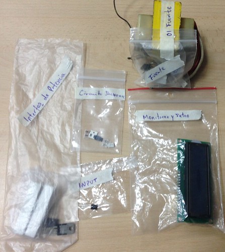
I also defined the way the elements would be distributed; I opted for a configuration of Modules in order to develop them one by one. Then, I obtained the first diagrams and component lists. I started to search and/or buy the electronic components and materials.
The defined circuits were:
|
|

Round 5:
With the simulation phase finished, the fabduino manufactured in input devices class was set up. Operating tests were made, IDE Arduino test programs were recorded.
|

Round 6:
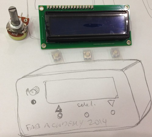
Subsequently, I checked the correct operation of the code developed during the simulation; for this purpose, I connected a potentiometer to a protoboard, in order to simulate the temperature sensor, a LCD, another potentiometer to regulate the LCD contrast and I saved the code in an Arduino Uno card.
|

Round 7:
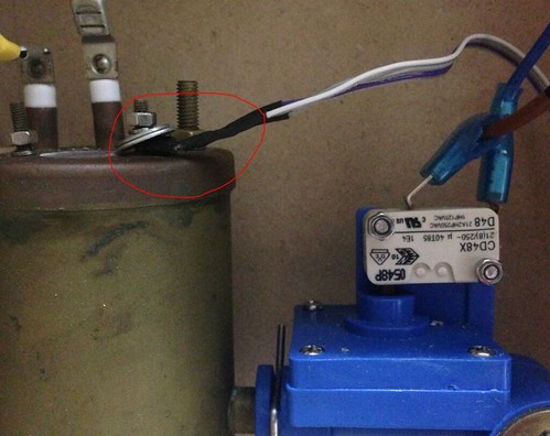
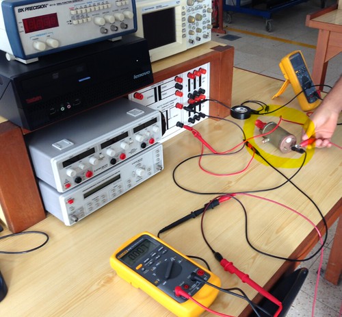
I got an old electrical water heater, and I took the heating resistance and, since I did not have the technical specifications, I made the corresponding measurements to identify: the correct operation, the ohms value and amperes consumption. These data was necessary to calculate the component capacity and design the power interface.
|
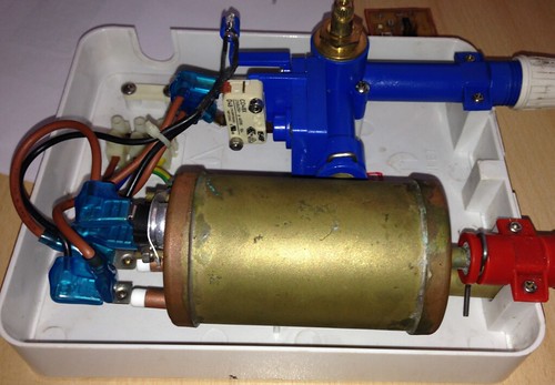
With the LCD and the heating resistance finally operative, I started to make drafts of the water heater. The second step was to make the case setting and place the pipes to locate the flow and temperature sensors.
|

Round 8:
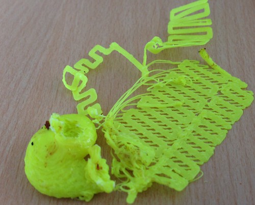
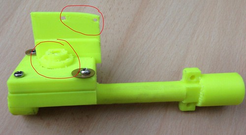
I designed a 3D piping, to locate the flow and temperature sensors. However, after several printing tests, the pieces did not fit correctly and that would cause a leak. I decided not to use the designed pieces and reuse the piping of the recycled heater. (In the future, I should look for a professional printer in order to obtain higher quality printed pieces).
This caused that in my first prototype the temperature sensor should be located in the water tank and would use the mechanical built-in flow sensor of the old system, which was operating.
Then, I started to work on the case setting.
|


Round 9:
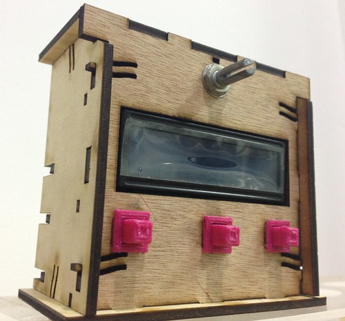
Design and manufacturing of the case setting. The design included a little box that may be located separated from the case heater. I tried to make a good looking case, since it would be the visible part of the prototype the user would buy. The case heater was planned to be installed and hidden from the user’s view; the internal part included holders to fix the LCD and the button cards, as well as a rear cover that could have been removed easily for checking, all in pressfit system. For manufacturing, 2D design was used; the cutting and the engraving were made by means of a Laser
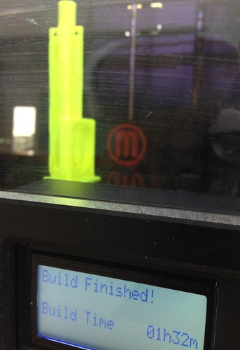
Epillog cutter in 3.1mm aeromodelism plywood. The buttons were designed in 3D and printed in a MakerBot Replicator 2x printer.
Two units were prepared, a testing one and the other with modifications and final engraving.
(Click for -->see photos album)
|
Round 10:
The next step was to make the case setting operative with the test circuit prepared before to test the microcontroller code. Then, the Arduino UNO card had to be replaced by the Fabduino card we previously made; the code was saved in the processor and the connections to make the it work along with the case setting were made.
|

Round 11:
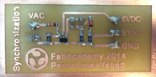
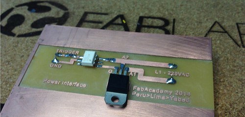
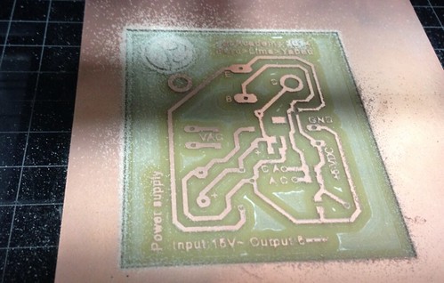
Then, I made the circuits: synchronization, power interface and power supply. The idea was to have the circuits ready so that they can be assembled and work together immediately. Only a dream.
|
|
|
Round 12:
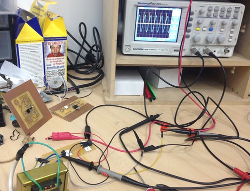
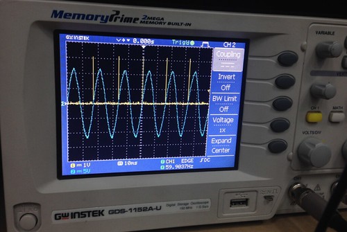
Once the three circuits were ready, I tested them one by one and then I connected one to each other. I started with the synchronization circuit, which generated the planned pulse, but when connected to the fabduino it stopped and after the tests the Opam component of the synchronization circuit burnt out. After several attempts, I had to modify the microcontroller program so that this prototype version may work without it. Once an operating prototype was obtained, I could turn back to see what was failing.
|
Round 13:
The power interface circuit tests were performed without problems.
|
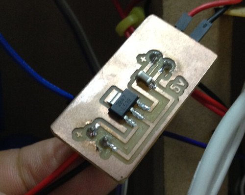
Round 14:
When testing the 5v regulated source I made, it operated well but unfortunately, when connecting it to the synchronization circuit it broke. Therefore, that card was not used in the prototype. Below, I detail how I solved the current feeding.
I discovered that I should not feed the synchronization circuit output with the 5vdc generated by the same transformer feeding the synchronization circuit.
In this project phase, the case setting was operative and tested, as well as the heater resistance, the card with the microcontroller (fabduino) was programmed and working with the temperature sensor and finally the power interface was also ready.
I decided to postpone the improvements for later, once I have finished the design and the case heater was made.
|

Round 15:
Design and manufacturing of case heater: in the design I took into account enough space to include three areas: in the left top, the high voltage heater resistance; in the right top, the area for low voltage electronic cards, and total division to separate in the low part an independent area for hydraulic flow (in order to separate the electronic part from the water, and to prevent any problem).
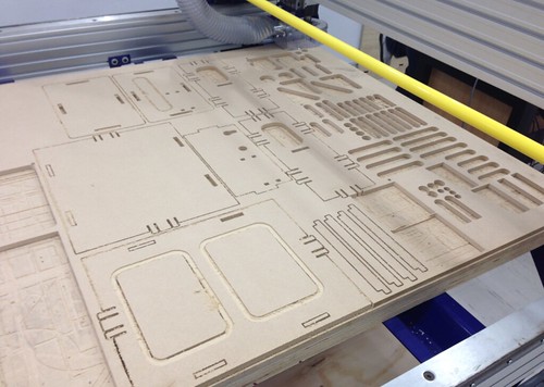
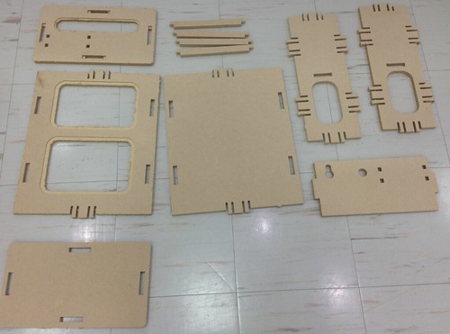
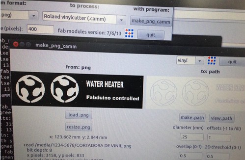
I also took into account to leave some open spaces in the front parts and in the top and cover them with transparent acrylic to allow the viewing of the inner parts of the prototype, from the top and from the bottom. For manufacturing, I used 2D design, 12mm MDF and CNC ShopBot milling cutter. Three processes were performed: Lace at two depths, inside court and outside court.. In order to cover the opened spaces, 3 mm transparent acrylic sheets were used; these were cut with Laser, so that they may fit by pressure. Finally, I added a decorative feature with a sticker of FabLab logotype, made with the vinyl cutter.
|

Round 16:
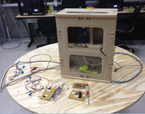
Case heater assembly and circuit installation
The side walls were assembled to the main piece by using a mallet; then, the front and rear plates were placed posterior. Then, on the ground, the vertical strips were fixed to the main piece; they would be the rack for electronic cards. Finally, the top plate was placed.
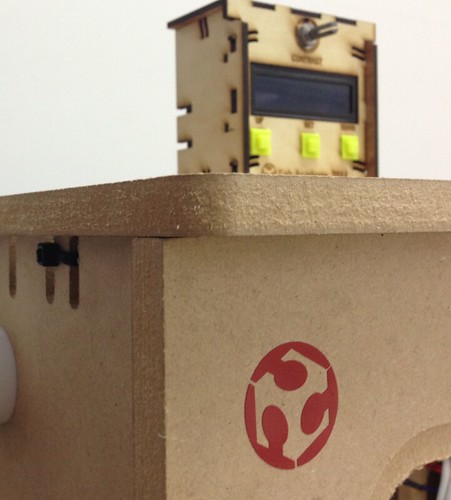
The heater resistance was put and we started to fix the electronic cards. The vinyl FabLab logotype was placed at the end.
|

Round 17:
First tests:
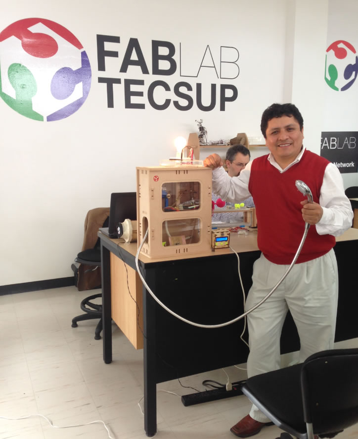
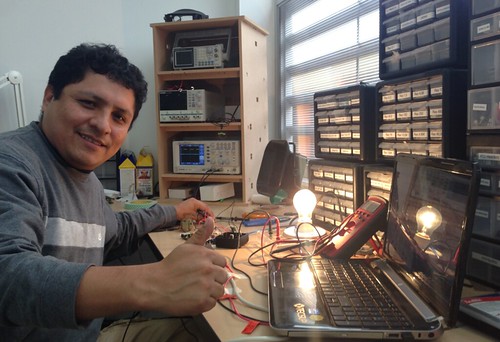
In FabLab we do not have a water supply to perform the tests, so I replaced the heater resistance by a 220v bulb, and placed the temperature sensor close, so that it may detect the heat sent out when it is turned on. Thus, the programming parameters were adjusted so that everything may work well. Considering that the loss of heat is not immediate, the program was made so that the system may work in a range higher than 2 degrees over and below the value fixed by the user (this can be reprogrammed anytime). The system would turn the resistance on if the sensor detects a value below the inferior range and would turn it off when it surpasses the higher value.
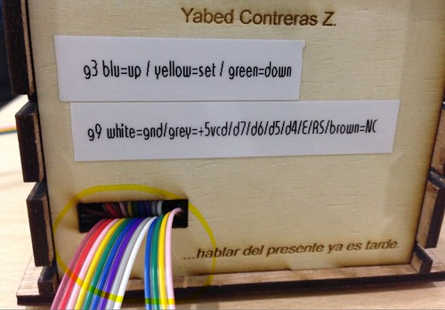
During the first steps, a unexpected failure was detected in the LCD (suddenly, it showed illegible characters), the contacts and connections were verified. After reviewing and disassembling almost the whole project, I tried changing the communication cable by a UTP cable. After the change, the problem was solved, but the cable we used was too rigid and it was difficult to install it; finally, we managed to make it work.
|

We had a problem with the current supply. The system worked well with the FTDI cable connected to the PC. However, when feeding the fabduino with a 5v regulated source, it showed operating failures. Different transformers were tested, as well as alternative rectification and regulation systems, but none of them could solve the problem. Therefore, for this phase, I decided to make the prototype temporarily operate by using voltage from the FTDI cable.
|