
>> Week 12, Apr 16: Output devices
Add an output device to a microcontroller board you've designed and program it to do something
 |
I’ve been learning on the go. I’ve not been able to investigate more about programming and technical details of each device. Now I’m learning about the functioning and control of leds. In this assignment, I will manufacture a Fabduino card, following the tutorial by Anna Kaziunas France Hello Fabduino. Then, I will prepare my own shield to mount a ledRGB, code and program the microcontroller, so that I can control it by means of Fabduino.
Description of the task:
The Fabduino details are included in the tutorial by Anna Kaziunas France Hello Fabduino. After cutting the PCB for Fabduino we proceeded to mount the electronic components. |
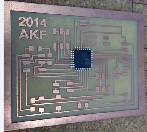 |
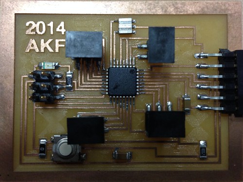
Finally, we have the Fabduino with all its components. Now, the next step is to activate it. |
 |
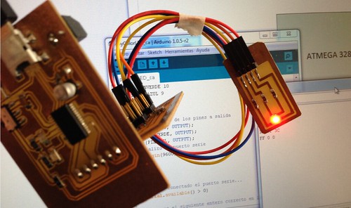
Pursuant to Anna Kaziunas France’s tutorial Hello Fabduino, the next step is to record the fabduino’s bootloader and load a short program to test the functioning. The fabduino is ready. |
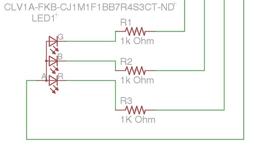
I designed a shield to install a RGB LED (CLV1A-FKB-CJ1M1F1BB7R4S3CT-ND) and control it by using the Fabduino. |
 |
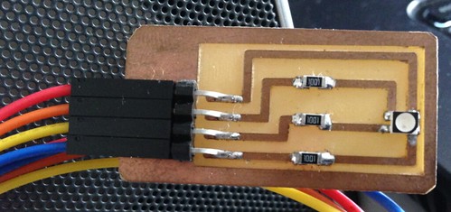 |
It should be noted that it is a RGB LED with a COMMON ANODE
|
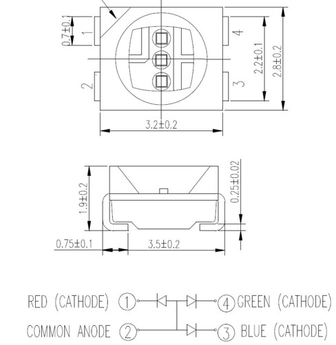 |
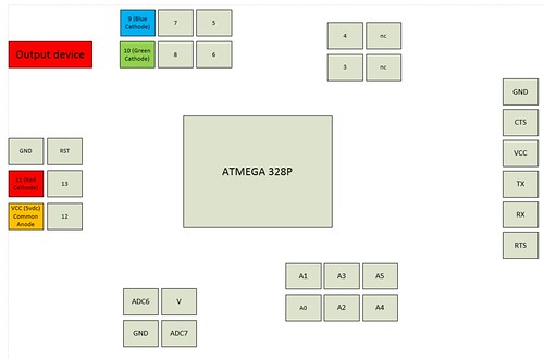
Diagram to connect Fabduino and RGB LED Shield |
 |
Use Arduino’s IDE to code the instructions to control the RGB LED. |
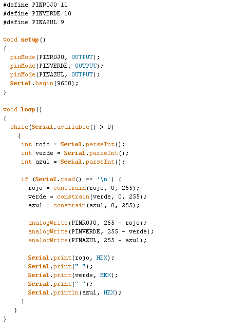 |
Then, we make the connections, we save the code in the microcontroller using the serial monitor of Arduino’s IDE. We validate the functioning. Thus, we control the RGB LED with the configuration “Common Anode”. |