
>> Week 10, Apr 2: Input devices
Measure something: add a sensor to a microcontroller board that you've designed and read it
The full understanding of this task is very important for the development of my final project. Considering this is the first time I work with electronic sensors, I decided starting by manufacturing the PCB which were given as model; thus, I could test and understand their functioning. For this purpose, I tested the temperature, light, sound and magnetic field sensors.
After completing the manufacturing and the functioning tests, I am surprised by the broad and diverse variety of sensors. I have learned that it is important to know their technical specifications in order to know their functioning parameters and to guarantee an adequate measuring. This information is essential to create the code and for the correct functioning of the program to be recorded in the minicontroller.
I don’t know programming, I am learning on the go. This chart shows the equivalence of AT Tiny 45 and 44 Microcontrollers Pins with Arduino UNO pins. It will be helpful when developing the code to program the microcontrollers by using the Arduino IDE.
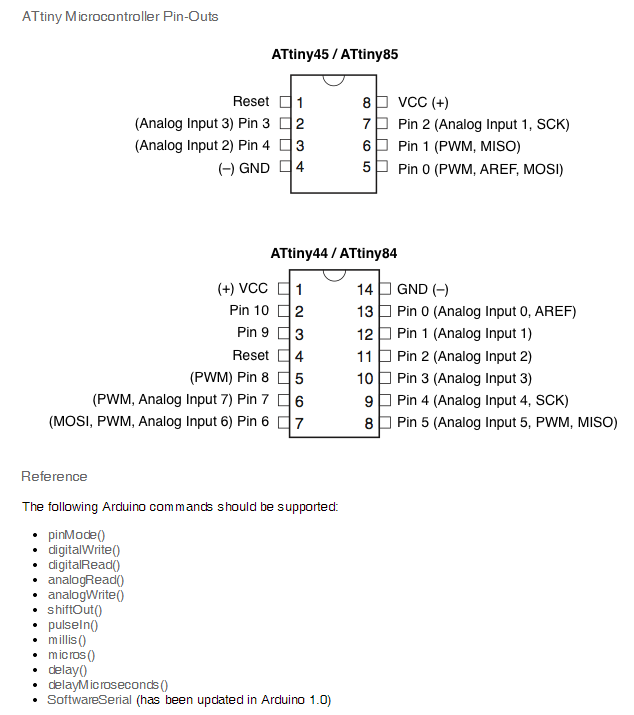 |
source: http://highlowtech.org/?p=1695
Below, you can find the report about the manufacturing of the exemplified electronic cards. This process includes the following stages:
>> Manufacturing electronic cards with sensors
>> Programming the cards
>> Validate the functioning with Python interface miniprogram
Electronic cards manufacturing:
Tools and materials:
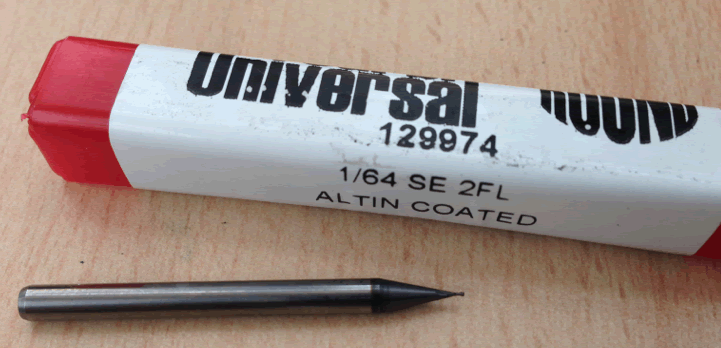
- 1/64’’ milling cutter
- 1/32’’ milling cutter
- PBC
- Traces for PCB
- Modela MX20
- Fab Modules
- Welding station
- Electronic components, detailed for each case
Remember: The 1/64 milling cutter is fragile. You should be careful when calibrating the Modela and when introducing the parameters in Fab Modules. |
 |
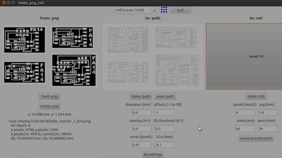
Organize the 4 cards’ traces to plot them in a single process. The parameters used may be seen in this screenshot. |
 |
For cutting, the 1/32 milling cutter is used; parameters are seen in this screenshot. During this part of the process, you should be careful and calibrate once again all the minicutter axis and do not move the PCB out of its place. |
|
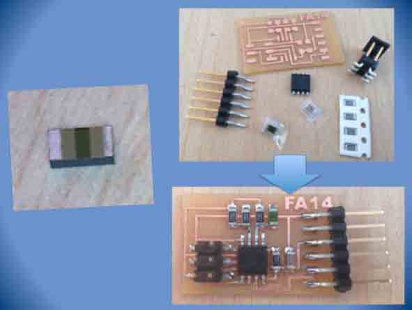
The cards were ready to continue the component welding process. A previous cleaning is advised. |
 |
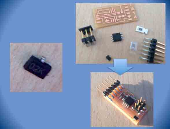
Make “Hello Light”:
|
 |
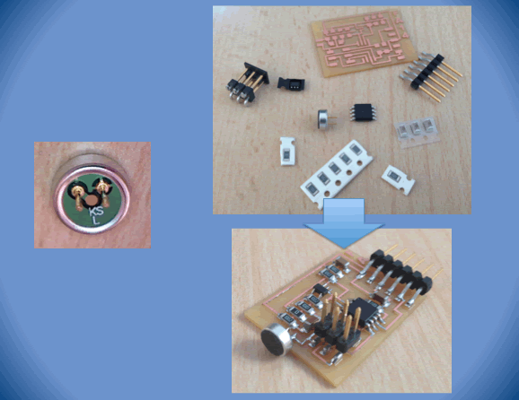
Make “Hello, Temp”
|
 |
Make “Hello Mic”
|
 |
Components for sensor hall effect:
|
 |
All the cards are ready to be programmed. |

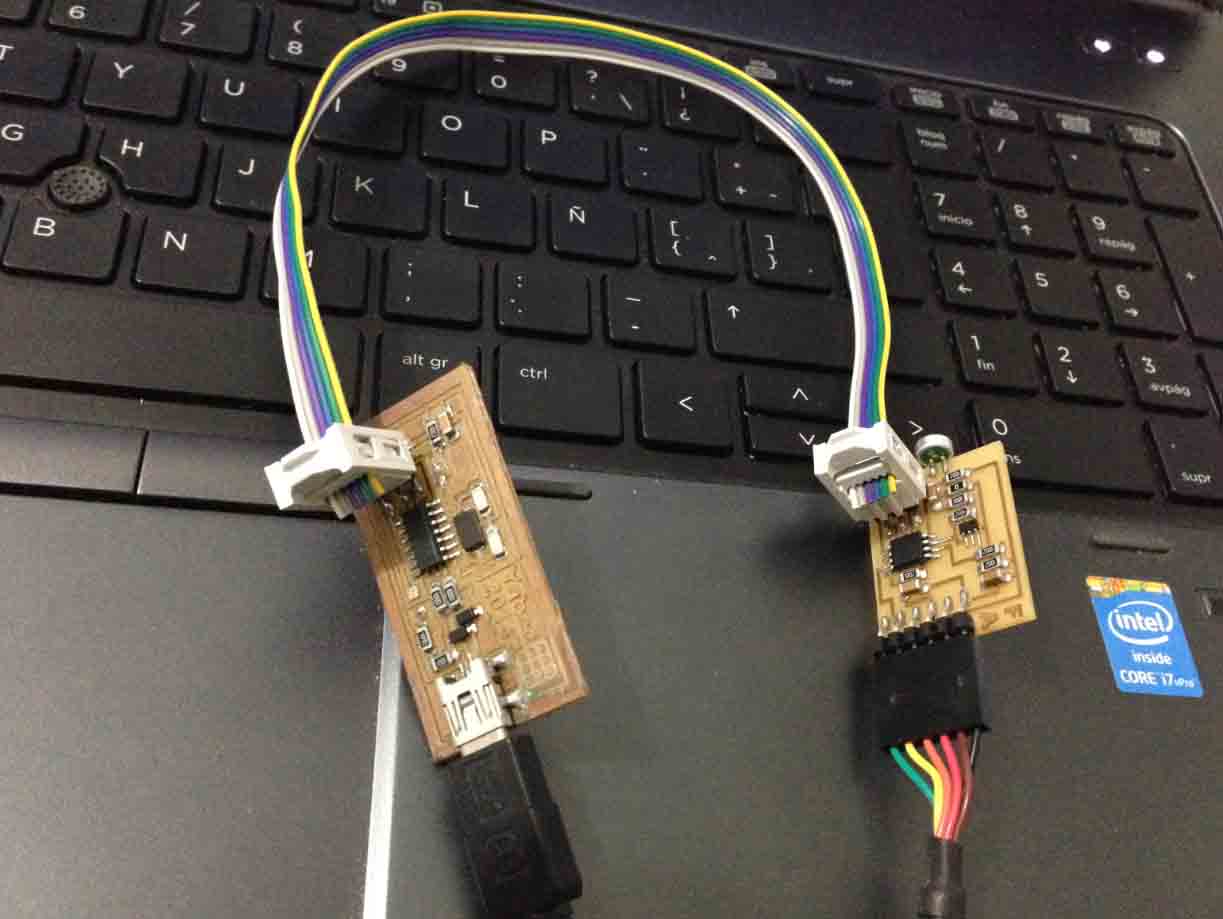
Programming the cards
Connect the FabISP to each sensor PCB and to the PC.
For programming in each case, follow this procedure:
1. Download the files with programming codes for each case.
- file: **.make
- file: **.c2. Enter the folder where the files you’ve just downloaded are located.
3. In the Mac or Ubuntu terminal, use the following command:
sudo make -f hello.mag.45.make program-usbtiny
Replace “hello.mag.45.make” with the name of the program corresponding to the sensor.
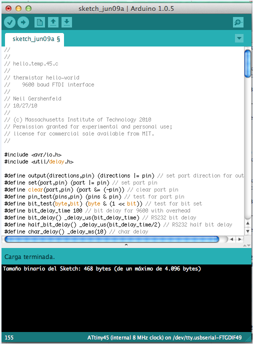
4. Other alternative is using the Arduino IDE to program the microcontroller. In the case of the examples, copy the file code with C extension in the IDE, compile and run the program. For more information, refer to this tutorial: http://highlowtech.org/?p=1695
Functioning validation
The Python interpreter should be installed to perform this task. (https://www.python.org/)
For Mac
To identify what serial port is being used, write down in the terminal:
ls /dev/tty.usb*------
MacBook-Pro-de-Yabed-Contreras-2:hello light ycontreras$ ls /dev/tty.usb*
/dev/tty.usbserial-FTG8MPK4------
In this case, the command to execute the program is:
python hello.light.45.py
  /dev/tty.usbserial-FTG8MPK4
see video: