>> Week 07, Mar 12: Computer-controlled machining: Make something big
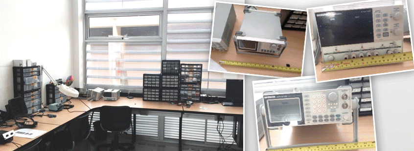
This time, the goal was to make a shelf to keep laboratory electronic oscilloscopes.
 |
Materials:
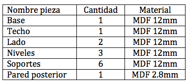
- A 12mm MDF sheet, 1220 x 1840mm
- A 2.8mm MDF sheet, 600 x 900mm
Tools:
- ShopBot Milling Machine
- Milling cutter 1/32¨
- Milling cutter 1/64"
- Electric screwdriver and bolts to fix materials to ShopBot
- Mallet
- Vacuum cleaner
Software:
- Autodesk Inventor 2014
- Adobe Illustrator cc
- PartWorks
- ShopBot3
>> Design piece of furniture
>> Plotting in ShopBot
>> Assembly
Design piece of furniture
First, I measured the oscilloscopes, evaluated each oscilloscope’s weight (in order to determine the material to be used), and confirmed the shelf’s functionality with the laboratory coordinator (client).
 |
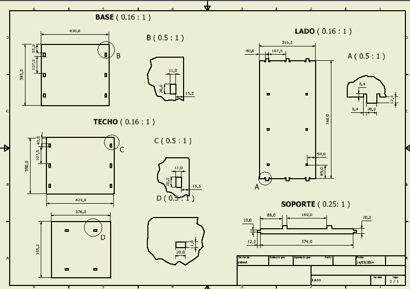
Autodesk Inventor 2014 was used to design each piece; the assembly was simulated and the number of pieces and their corresponding measurements were determined in the same program.
 |
 |
 |
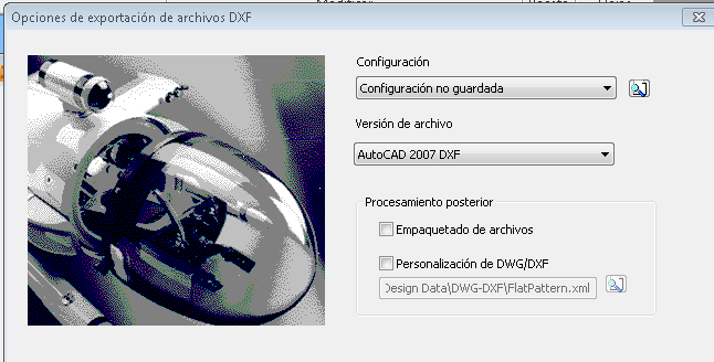
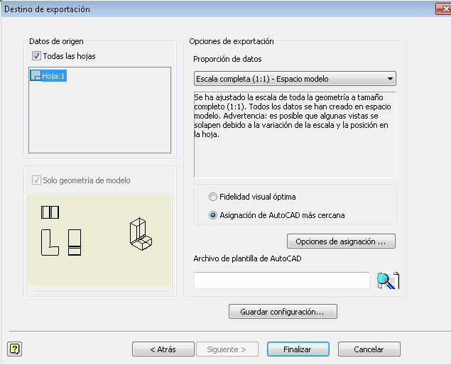
When I finished this stage, I exported the plot file containing the measured pieces (.dwg) to .dxf (2007) format; then, I prepared the file to be plotted in Illustrator. It should be noted that the export is performed in a 1:1 scale.
Plotting in ShopBot
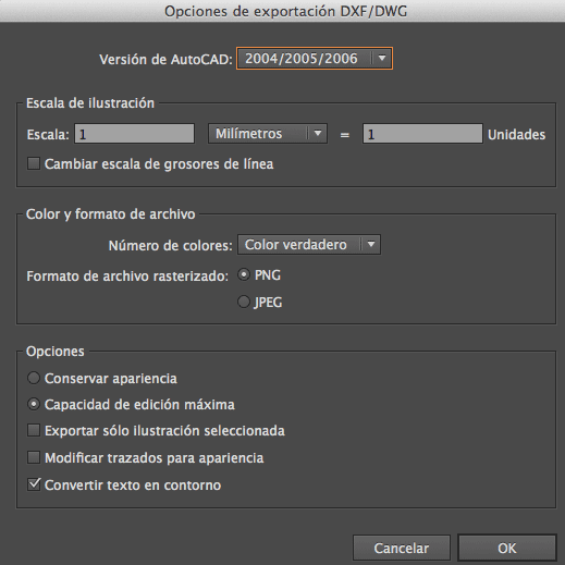
To plot in ShopBot, we need a file containing all pieces adequately distributed, in order to optimize the material consumption. For this purpose, I used Adobe Illustrator, where I verified each piece’s measurements, the closure of polygons, and the thickness of lines to be used. I added the required amount of pieces, I distributed them in order to optimize material and finally I exported the file to be plotted to the DXF (2004) format, so that PartWorks, the software used to generate the ShopBot cutting path, may read it.
Once the file with the pieces to be plotted was ready, I prepared the ShopBot.
I cleaned the sacrificial plate to make the material uniformly match and to make the cuttings correspond to the expected measurements.
I placed the 12mm MDF sheet on the ShopBot
I run PartWorks
I imported the .dxf file
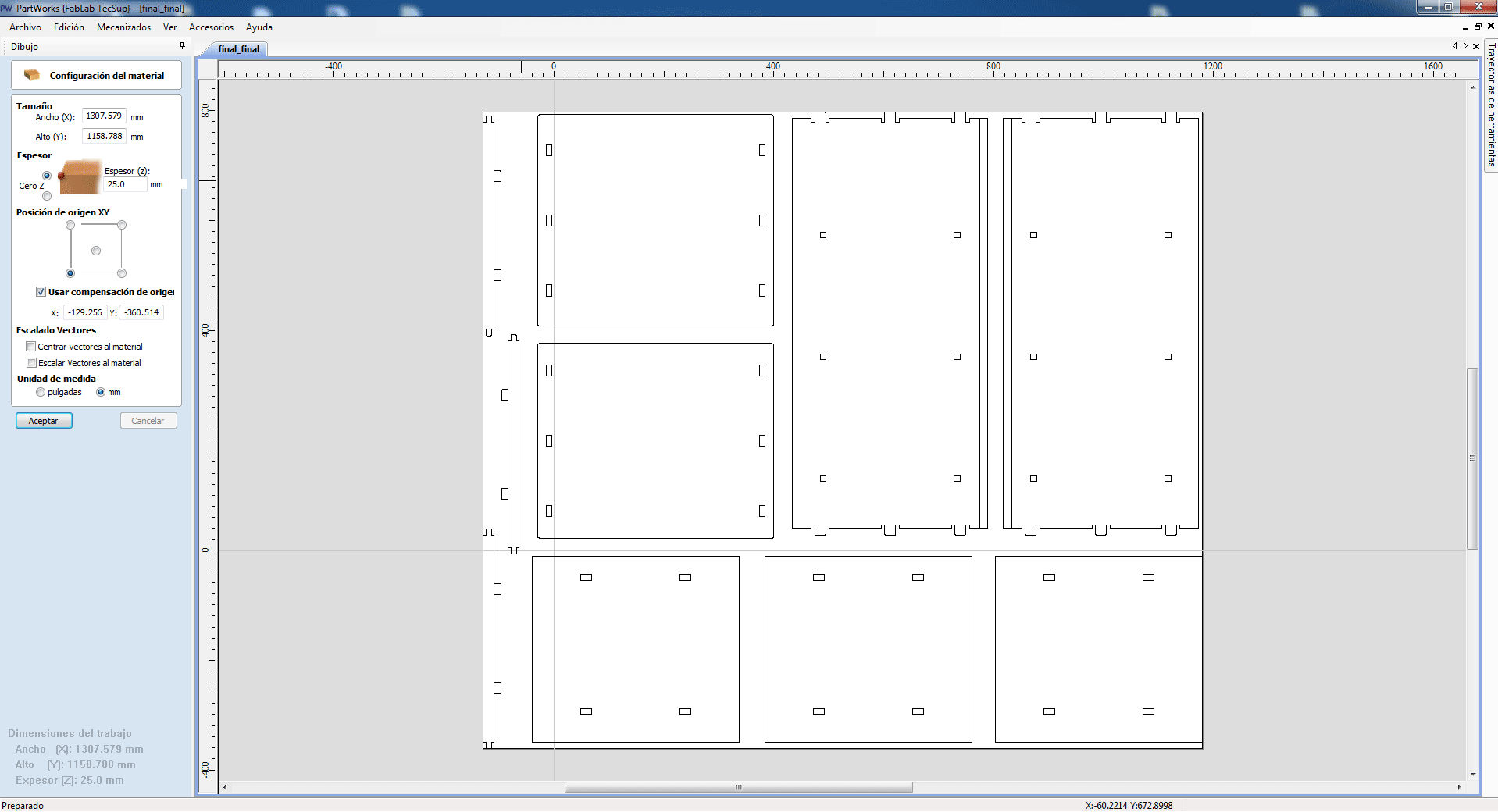
I configured the material size, thickness and the position of XY origin. I did not use origin compensation. I set the measurement unit in mm.
I opened ShopBot 3, I order to calibrate the machine; I started with Z axe, then XY axis
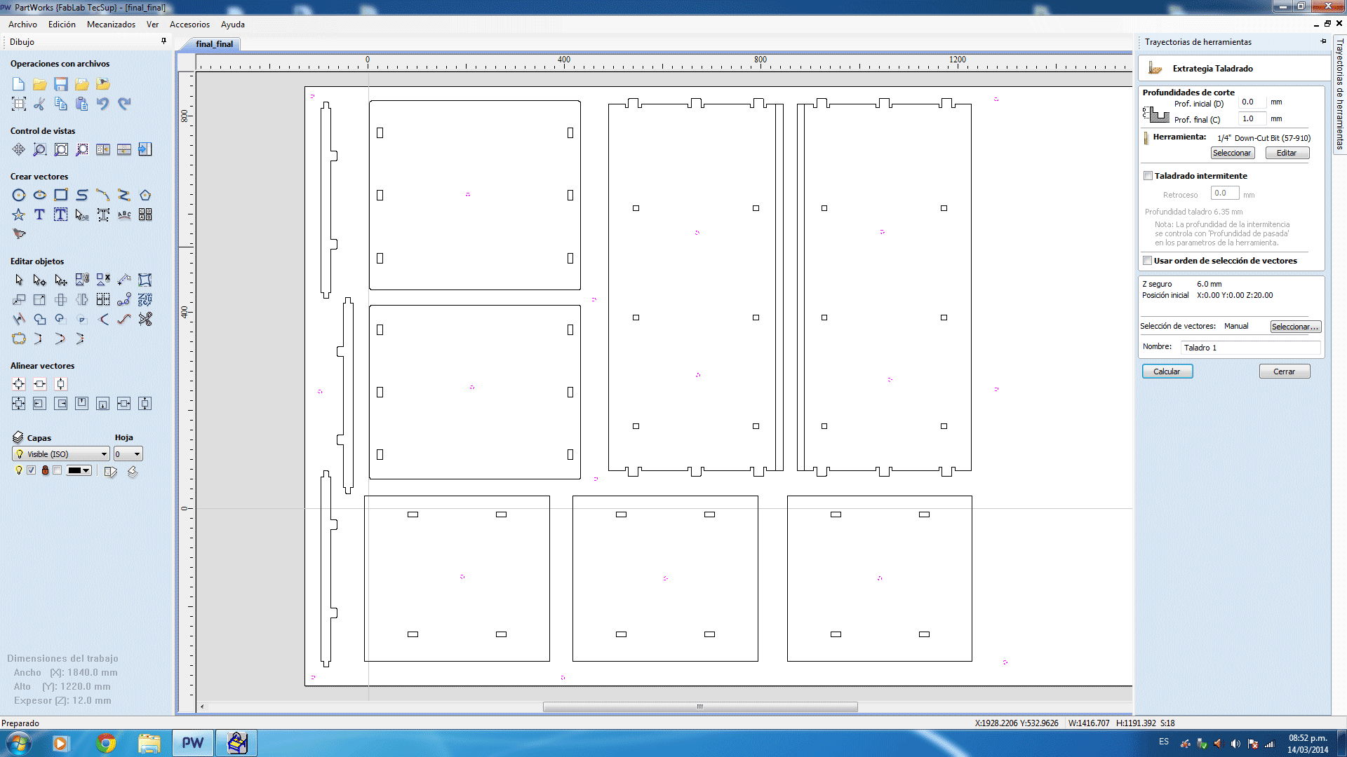
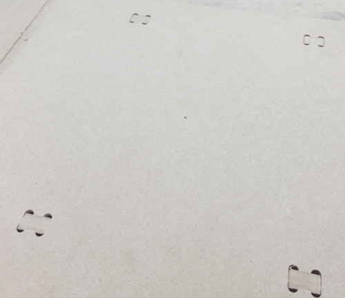
I returned to PartWorks and generated the first path to mark where the MDF setscrews will be placed on the sacrificial plate.
For this purpose, I set the points where the screws will be placed by using the command "Create circle" (taking into account the diameter of the 8mm screw heads)
Then, I selected the circles I created and generated a 2mm depth drilling path. The milling cutter diameter was 1/32’’.
I outlined the path and I verified and recorded the file in .spb format.
Note: The circles should be located in a position to prevent a collision between the milling cutter and the setscrews during the plotting.
Then, I returned to ShopBot 3 and opened the file with the drilling path. This was a .spb file.
I run the file by clicking on "Start": this creates the G code and then verification messages appear on the screen. Finally, before starting the process, it demands to activate the milling cutter rotor. For this purpose, we should press in ShopBot the green button "Start".
Once the rotor has reached its working speed, we click on screen the option “Continue” to start the drilling path.
Note: In case of any mistake, the blue button, Reset, may be pressed; and the process may be started again.
If there is any hazard, the RED button may be pressed to immediately stop the machine. Goggles and earmuffs are recommended to prevent permanent damages.
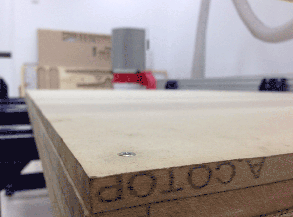
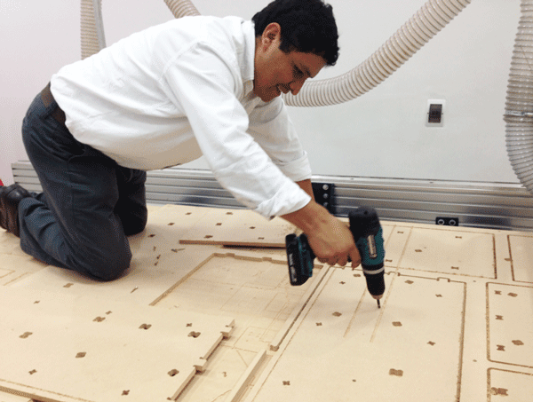
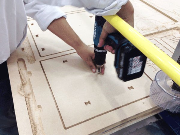
Following the path outlined in ShopBot, I anchored the material on the sacrificial plate, using some screws; screw heads should not protrude beyond the plate. Thus, I prevented any collision between the milling cutter and the screws. With the material fixed, I generated the other paths in PartWorks.
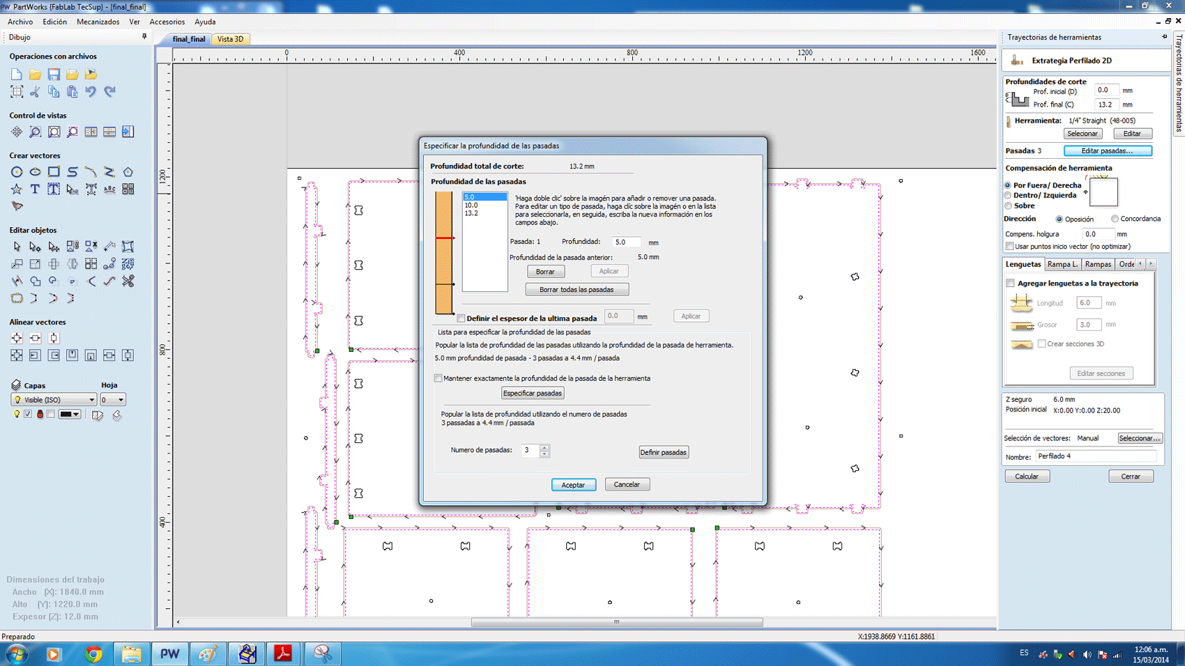
For the rest of the work, I created "Side" paths.
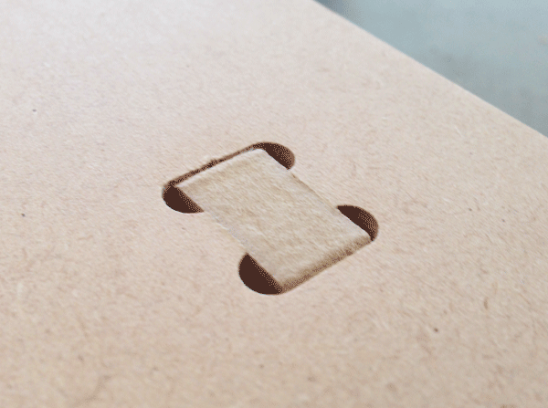
- For orifices, I set the path within the cutting line, not over it.
- To cut each piece, I set the path outside the cutting line.
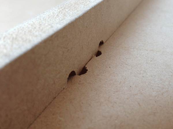
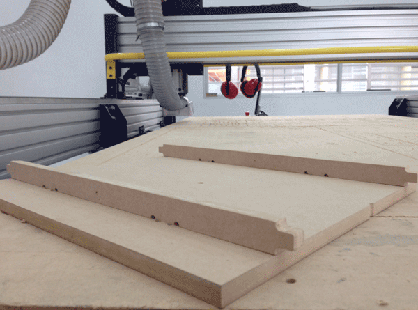
- To make the bevel to hold the posterior panel, I set the path ON the cutting line and by using a smaller diameter milling cutter, 1/64¨
All the time, the safety measures should be taken into account: Goggles and earmuffs Problems that arose during the plotting:
- The head did not go over the expected path. I noted that zero in PartWorks was not the same than the machine’s zero. I resolved it by correctly adjusting zero in PartWorks.
- Perforations did not correspond to the design. I noted that the milling cutter diameter had not been considered; thus, the cutting did not correspond to the design measurements. I resolved it by setting the correct diameter.
- The system does not allow making fitting movements to opened vectors that do not form polygons. I wanted to make a fitting path to perform a 4mm depth line to fit the posterior panel. I resolved this by using a side path.I learned to change the milling cutter. The procedure below:
- Put the head on a place which allows you managing it easily.
- Turn off the machine.
- Take the milling cutter plastic protector down
- Using two wrenches loose and replace the milling cutter
- Adjust tightly
- Return the milling cutter protector to its place.
Finally, the setscrews are removed in order to use the pieces in the following assembly process.
Assembly
For this procedure, I used a mallet to prevent damaging the material
I started the assembly, putting the brackets and holders together. Then, I verified that the pieces were adjusted without problems.
Posterior view of the piece assembly
One of the stands with its two brackets assembled
Upper view: this is how the assembled and adjusted pieces look
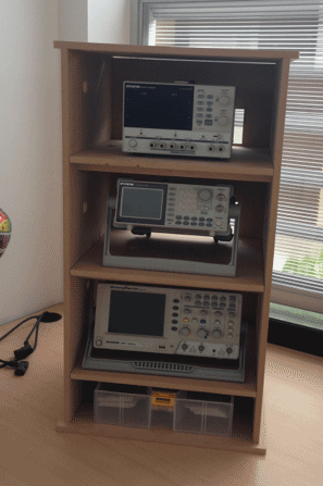
This is how the piece of furniture will look.
This is the shelf with the electronic oscilloscopes
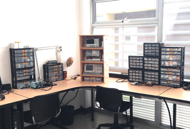
Finished shelf on its final location.
The work files are located in the following repository:
Find folder A07, in Repository
Note:
Thanks to our instructor Roberto Delgado in the development of this assignment. Taking into account our labor load, and in order to fulfill the goal in the indicated terms, it was necessary to use the lab in non working hours.