>> Week 06, Mar 5: Electronics design
For this assignment, we will follow the steps below:
>> Redraw the "echo hello-world" board
>> Add (at least) a button and LED (with current-limiting resistor)
>> And making
>> About simulation
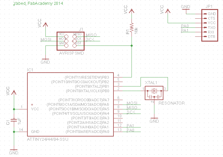
Redraw the echo hello-world board
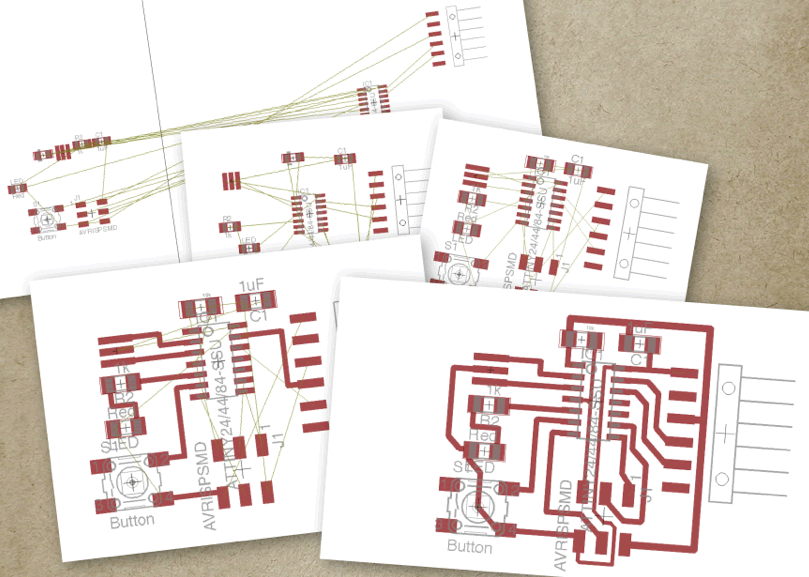
From the original circuit graphic "echo hello-world", provided for this assignment, and using EAGLE software, I outlined it and I obtained the diagram of the original circuit.
Materials:
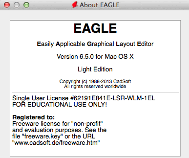
- Software EAGLE Light Edition
- Echo hello-world board
Sequence and commands used in EAGLE:
- Get the original circuit board: echo hello-world
- Install EAGLE software
- Download the components’ libraries from the following link: eagle_libraries.zip
- Decompress and save in the EAGLE’s libraries folder.
- File/New/Schematic, to create a new schematic diagram
- Library/Use, to load the libraries
- Edit/Add, to include the library components to the diagram
- Net, to make the connections
- Name, Value, to register the adequate names and values of each component
- Label, to include in the diagram relevant information for understanding and to link components
- Move, Mirror, to locate the components in the template
- Delete, to delete the connections or components
- Tools/ERC , to verify program errors and warnings
- Export/Libraries, to export in a .lbr file all the components used in the diagram.
 |
 |
 |
Add (at least) a button and LED (with current-limiting resistor)
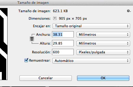
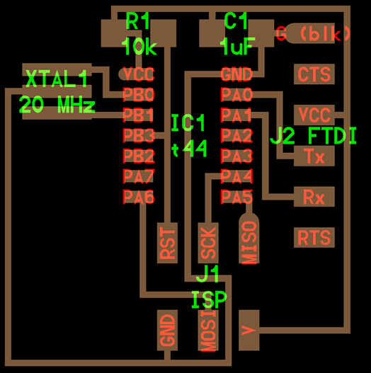
Using the original circuit scheme we obtained in the previous step, I added the schematic diagram the switch and the led with the current-limiting resistor. From this new scheme, I prepared the board image I used to manufacture the card. To customize the design I used Photoshop.
Materials:
- EAGLE software
- Adobe Photoshop
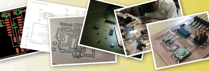
And Making
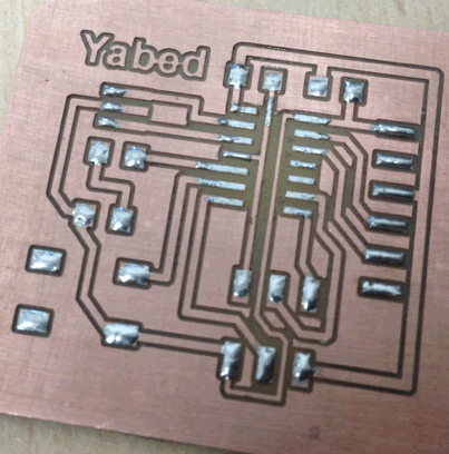
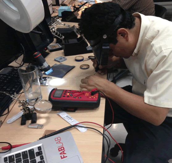
With the design and the board image ready, I plotted the PCB in the milling machine and then I welded the electronic components.
Finally, I checked for continuity with a multimeter.
Surface assembly materials and components:
- PCB board
- ATTiny 44
- Cristal 20MHz
- Capacitor 1uF
- 1k and 10k ohms Resistors
- Switcher
- Led
- Pinheader 2x3
- FTDI 6 pines connector
Equipment:
- Roland Milling Machine
- Fab Modules
- 1/64 and 1/32 milling cutter
- Welding station
- Multimeter
- Magnifying glasses
About simulation
I made a research about simulation. I did not have enough time and I only was able to review some programs. Currently, I am learning to use simulators. However, after this short research, I think the best options to simulate circuits with microprocessors are SPACE standard simulators. I am currently checking the Space-based OrCAD simulator.
Reviewed simulators are:
- Partsim: http://www.partsim.com/ An elemental simulator
- 123D Circuits: http://www.123dapp.com/circuits An elemental simulator
- Cadence OrCAD:
http://www.cadence.com/products/orcad/pages/default.aspxNote:
Thanks to our instructor Roberto Delgado and his collaborators team in the development of this assignment.