This is a weblog for the 2014 Fab Academy class in Providence, Rhode Island. The class is taught locally by Shawn Wallace and globally by Neil Gershenfeld from MIT's Center for Bits and Atoms.
This site will be updated weekly with project proposals, research, progress, and final output.
I can be contacted at nickolaspeter@gmail.com
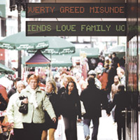
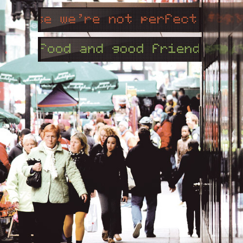
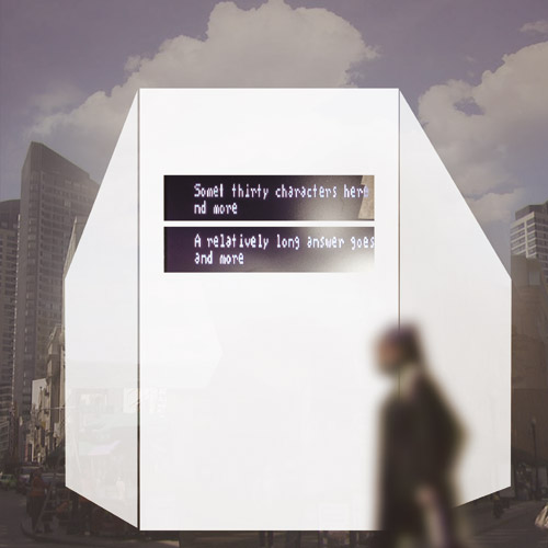
Ideally the work would be situated in a public space with a variety of people passing by. Above is a rendering of it in Downtown Crossing in Boston.
Note to self: consider how the information/prompt is presented next to the work (if at all).
I have submitted this project to the Boston Public Space Invitational.
←
My proposal included a diagram of the technical parts of the project, as well as a writeup of the thinking, available here:
←
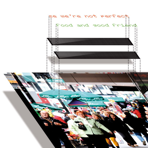
Schematic of Photoshop mockup.
I started with the photo as the ground layer, added two black boxes with shine to mimic marquees and used the free font Ecran Monochrome for the LED text.
Download Photoshop file: led_01b.psd
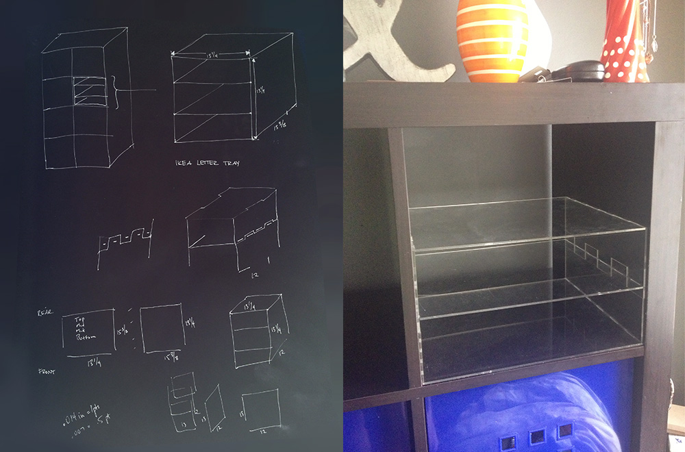
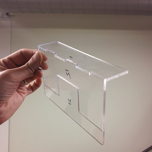
The goal was to make a modular press fit box/shelf design that would turn one of the cubicles of an Ikea shelf into a letter tray. Since the dimensions of the cubicle are 13"x13"x15" deep, I had to reduce the depth to 12" to fit a 2'x1' bed.
However, even at that size, it would require a sheet of acrylic per side / shelf, necessitating 6 sheets, and resulting in ~40% waste.
In order to maximize efficiency and to make the construction modular I decided to attempt a segmented side wall design with vertical teeth, and gaps for the shelves.
←
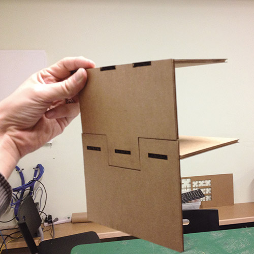
Cardboard proof of concept. It looks like the joint will connect the vertical wall pieces and the horizontal shelf piece. In fact the shelf teeth strengthen the walls.
←
Test in acrylic, the vertical teeth are surprisingly effective, but are susceptible to lateral rotation.
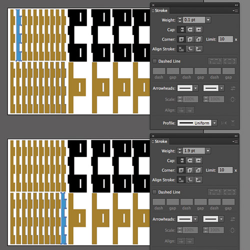
Without knowing any CAD scripting, I decided to see whether it was possible to find a magic number in Illustrator by adding strokes from 0.1pt to 1.9pt (in 0.1pt = 0.035mm increments) and seeing which resulting thickness fit most snugly.
To outline a stroke:
Object > Path > Outline Stroke
Window > Pathfinder > Unite
Download: boxkerf_01_B.pdf
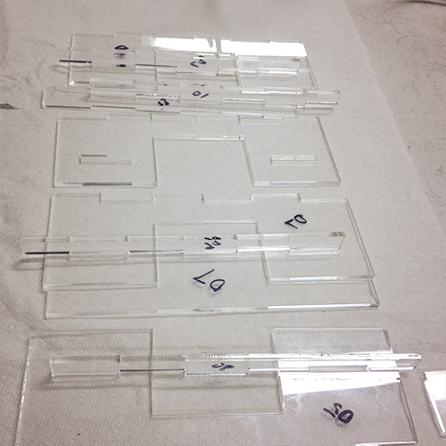
4 sheets at 85% efficiency.
It turns out that any amount of stroke between 12 and 14 decipoints result in a tight fit.
←
From the top: 7+6, 1+13, 7+7, 5+8
At 0.7 pts one of the middle sidepanels broke, resulting in two shelves instead of three, so I suspect 0.6-0.65 pts would be optimal.
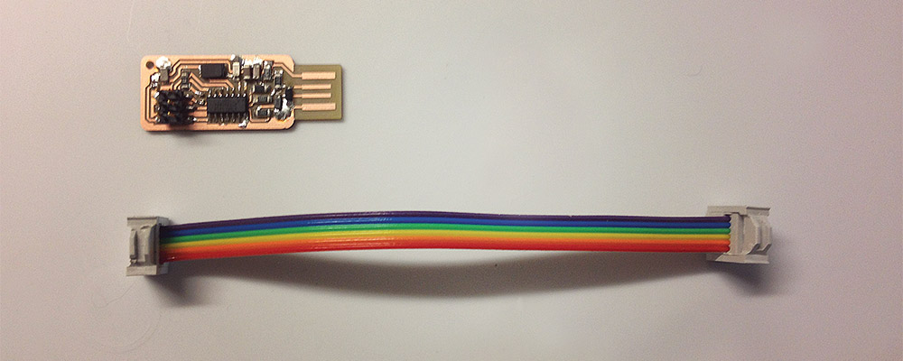
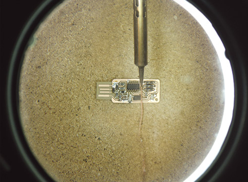
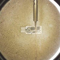
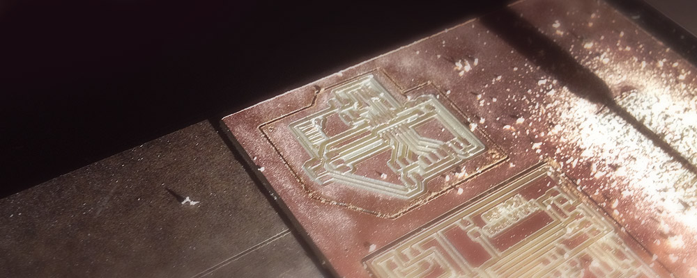
Milled on a Roland Modela, stuffed by hand. Oh what fun.
We suspected the sacrificial surface or the two-sided tape made the platform uneven, so we increased the Z depth for the bit from -0.1 to -0.13 for cleaner traces.
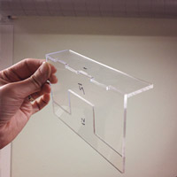
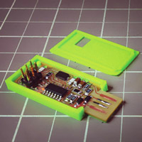
What's a Fab ISP without a shiny case.
←
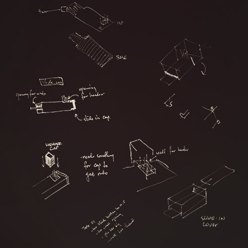
Miscellaneous drawings for potential cases, including a closed slide-in model with end cap, a Zippo-style hinge, and top slip in cover (the latter two from classmates).
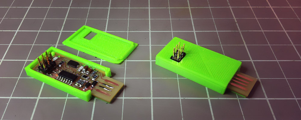
I settled on a halved top/bottom design since it could be done by extruding flat shapes vertically.
I took advantage of Andy's corner hole and designed a pin into the bottom half of the case.
←
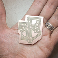
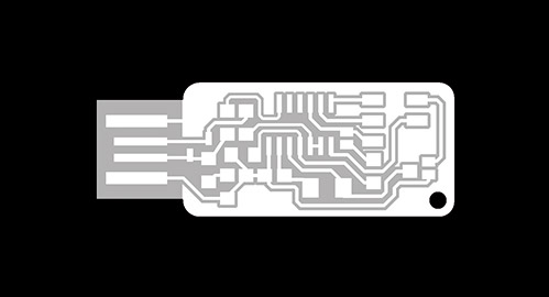
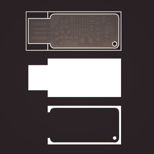
The starting shapes were created by vectorizing the board shapes, some booleaning, then stacking.
The PCB board isn't quite thick enough to fit tightly into a USB board, so a base lip is useful.
←
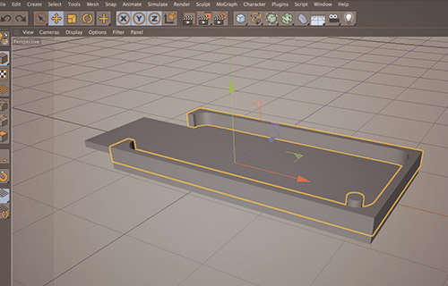
Here is the initial design at 1mm thickness for the base, and 2mm for the walls.
←
First printed attempt - inner opening too small, lip too thick, header opening too small (not shown), walls too short.
On the Replicator 2X, printing without a raft results in a smooth finish on top and bottom.
However, raft-less printing on the original Replicator resulted in warping.
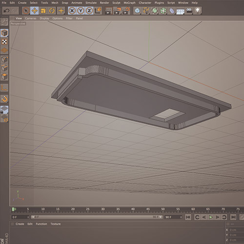
All problems fixed, optimal height for bottom base/lip is 0.5mm, and 3mm for the walls.
The model of the top half includes an extra downward extrusion at the USB opening to keep the board from moving vertically.
STL Files:
←
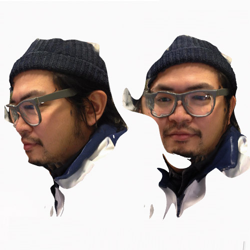
I used 123D Catch for iOS to scan my friend Gerard's face. It did a surprisingly good job with the left side of his face/glasses, but it showed tearing on his right side
Download STL: gerardSTL.zip
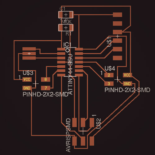
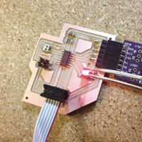
This is a version of the echo hello-world board but with two headers for the four available pins on the ATtiny84, making it expandable.
←
Pins 8 and 7 with power / ground on the left, 2 and 3 on the right (both sets in yellow). 8 and 7 are PWM, and 7, 2, and 3 are inputs.
←
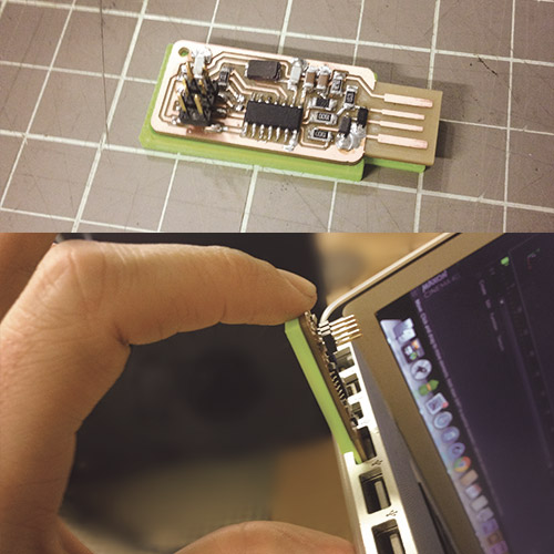
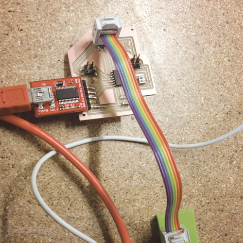
Testing to see if code will upload from Arduino IDE via Fab ISP.
Looks like it uploads (no errors at least), nothing input or output is yet attached, so we'll have to see for sure.
Eagle + trace/exterior pngs:
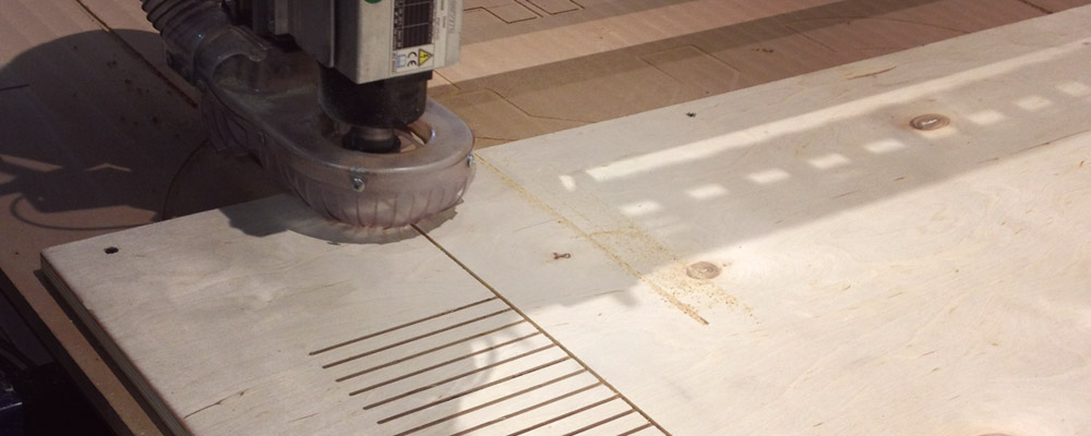
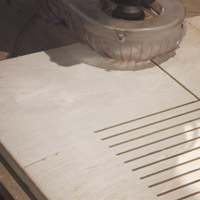
In order to make a chair I had in mind, I started this lesson by running a series of tests to understand the necessary density to kerf bend plywood.
←
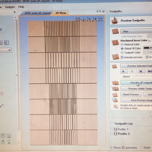
I set up a file with 4 different densities, in two lengths.
←
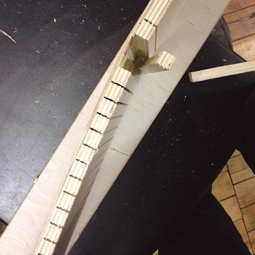
When bent only slightly, the "slats" would separate from the last ply, so I tried cutting with and against the grain on the plywood to determine if that was the problem.
←
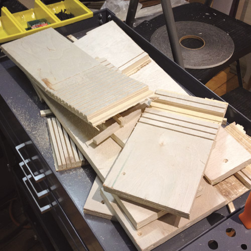
All of the boards broke fairly easily, I think a test of another plywood or other lumber is in order.
Also a test with through-cutting may prove to be more effective, as the joints would not depend on a single ply and glue.
Download: KERF_trials_01_toprint.pdf
←
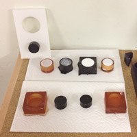
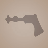
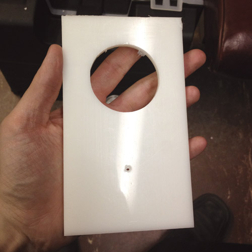
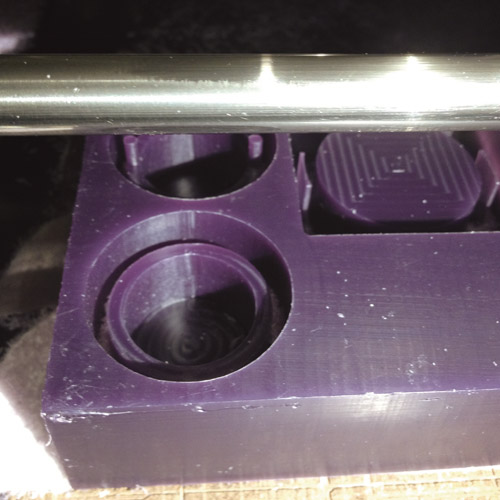
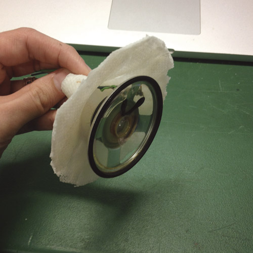
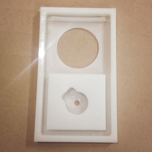
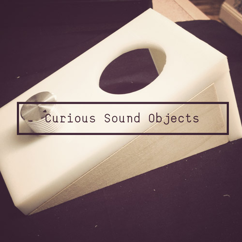
I decided to switch to HDPE and machine an enclosure for a one knob "Curious Sound Object" (video + audio synthesizer) that I have been planning.
This is the face, the circular hole is for the screen, and the little one is for the potentiometer.
←
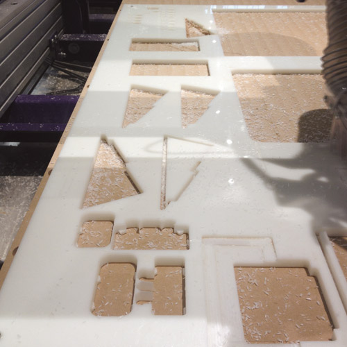
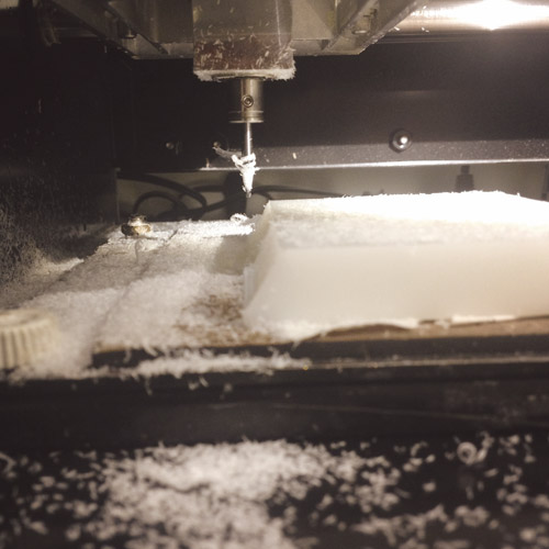
Machining the faces, also tried with wood.
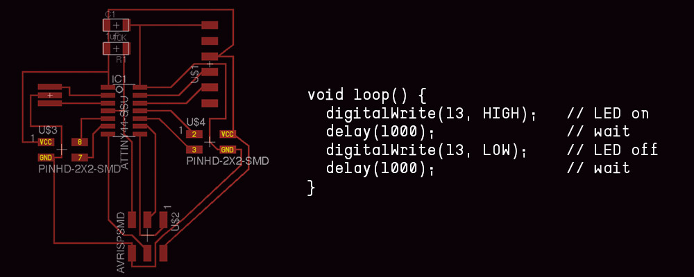
I started with Neil's code (above), but changed 13 to 3, which corresponds to pin 3 on the Robo board.
←
Yes, I'm holding the LED with pliers between 3 and ground. Also discovered that LEDs are directional.
Arduino sketch: Blink_pin3.ino
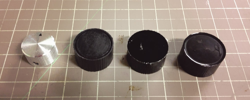
Every Curious Sound Object needs a nice knob, so I set up a one and two part mold, with the ability to mix and match to get flat topped knobs, and ones with an inset ridge.
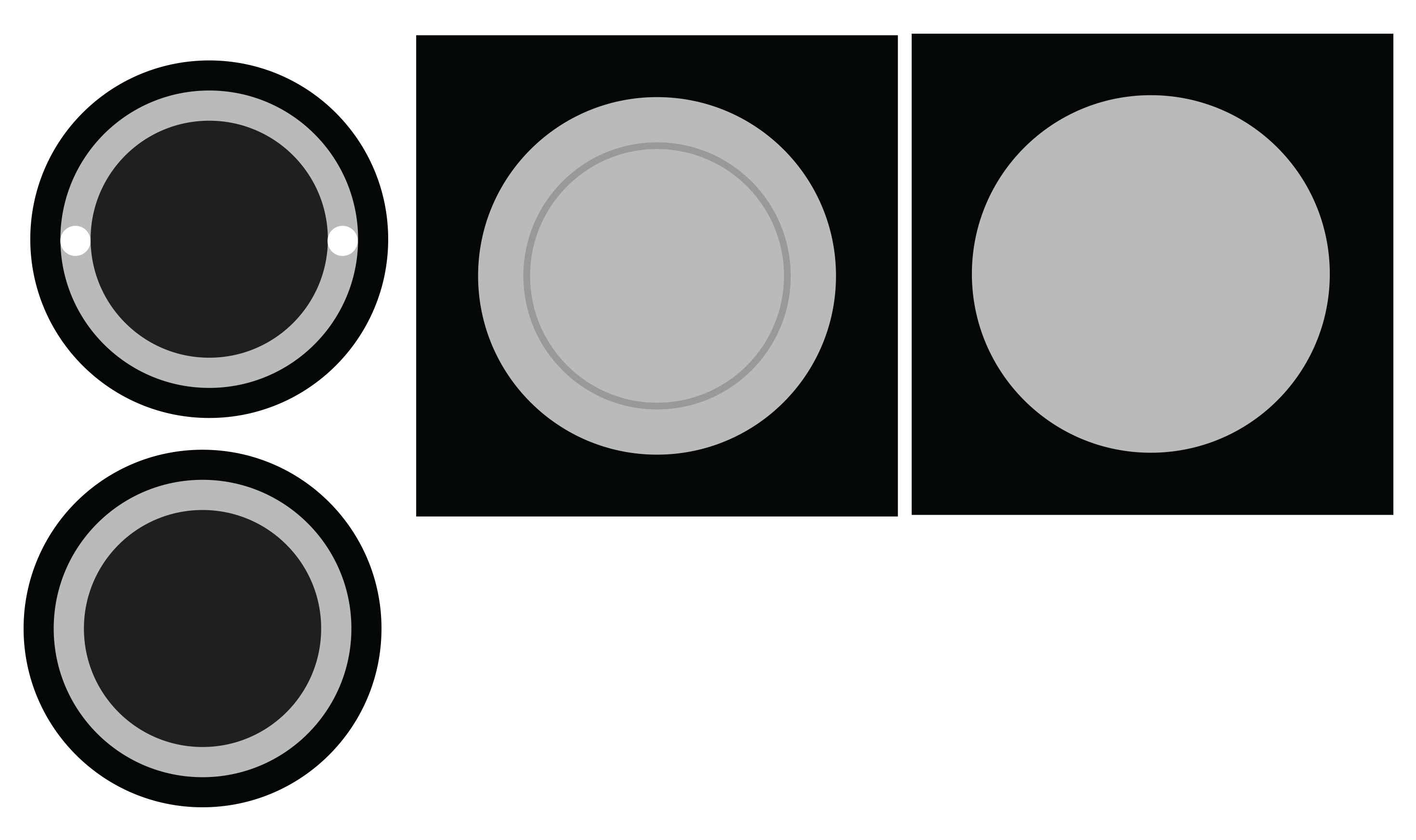
Download: knobs_01.png
←
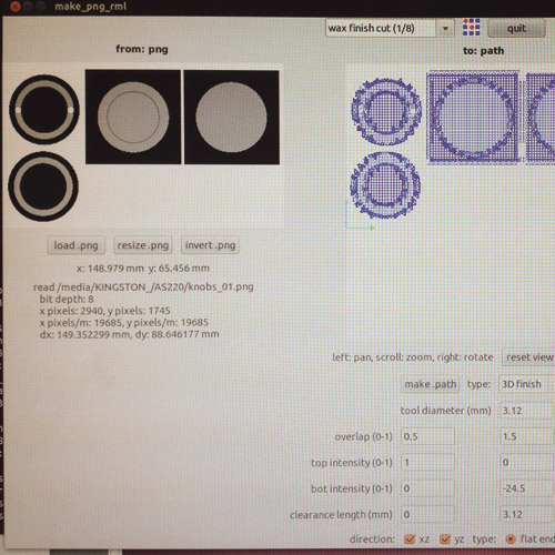
Since most of the Modela bits taper, I used a regular straight 1/8" Dremel bit for the rough pass, and the shapes had to be designed accordingly.
I then used a 1/32" bit with an 80% overlap (0.8) to get a glassy smooth finish on the top.
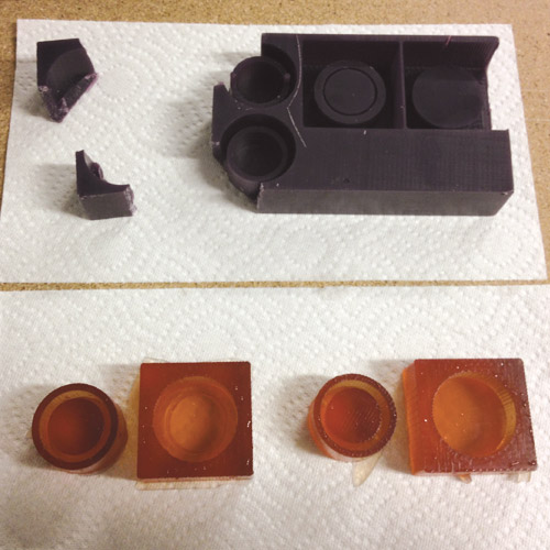
←
Resulting molds, everything looks good.
I had to break the wax to get the cornermost parts out, but was able to tape it back together to subsequently make more molds.
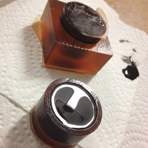
←
The two part mold allows for the creation of a surface relief (in this case a ridge).
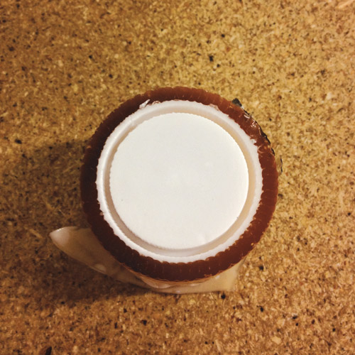
←
The one part knob ended up being the smoothest and shiniest.
←
Two part ridged cast, looks pretty good in white. I tried sanding the black version, but it ended up looking scuffed, the grit was probably too coarse.
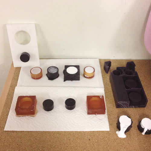
←
All of the tests on display, including one knob on the front panel of the Curious Sound Object.
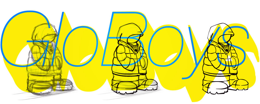

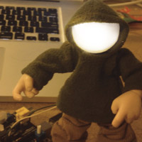
Several years ago I had an idea for a series of sound reactive toy figures, above is a drawing for C-Glo by my good friend and talented animator Dante Fabiero.
←
An early prototype of Brother Glorious I made in 2007 with just batteries and an LED.
←
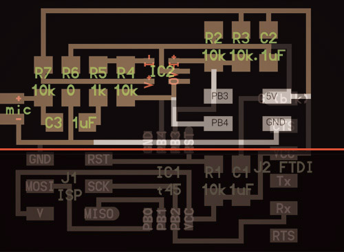
I started with the microphone board here and chopped off the microcontroller, FTDI and programming headers in lieu of a four pin header to interface with the Robo board.
Download: hello.mic.45.chopped.zip
←
The GloBoy loves techno.
The code here uses two input pins, one for reference. I was unable to figure this out, so instead I multiplied the two pins together, and using the map() funtion to convert the crazy values to 0-255 then send that to the LED pin.
Download: AnalogInput_Electret_works.ino
In order to further the sound object project, I experimented with reading the potentiometer, and sending that value from Arduino as MIDI via USB Serial.
Needs MIDI.h and Hairless MIDI
The two necessary lines of code are:
int analogValue = analogRead(A5)/8;
MIDI.sendControlChange(1, analogValue, 1);
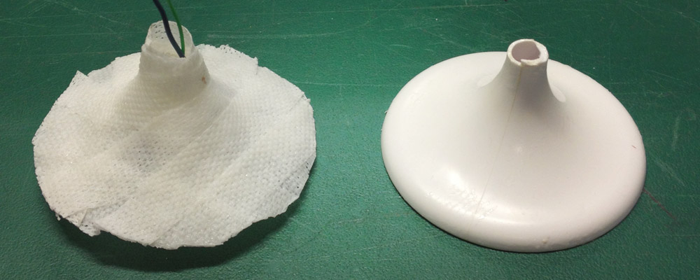
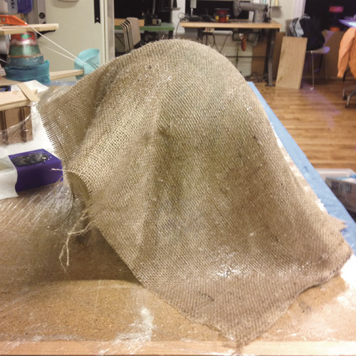
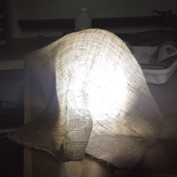
I then tried to see if it was possible to make a freestanding, but loose looking structure by covering an elevated plastic ball with burlap and then soaking it in resin.
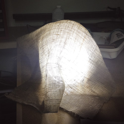
←
Resulting free standing shape, with a work lamp inside simulating a sphere.
Ultimately, it should have an elevated frosted glass sphere attached to the top of the burlap inside to really push the idea of a glowing ball floating off the ground.
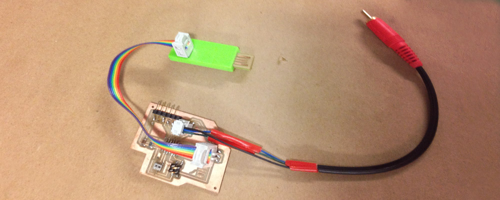
The ATtiny (above) does not support video out (at least not via the Arduino TV Out library), and is not one of the listed processors here.
←
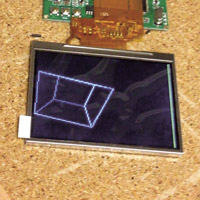
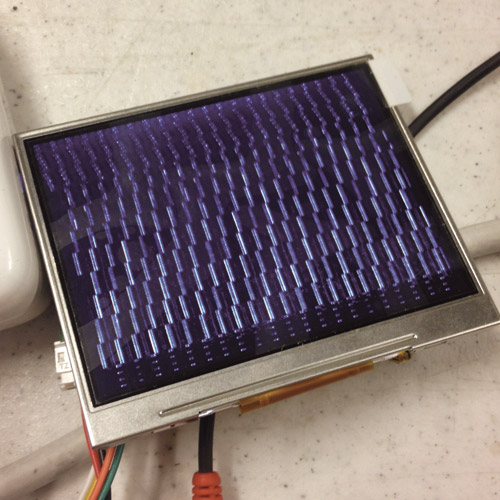
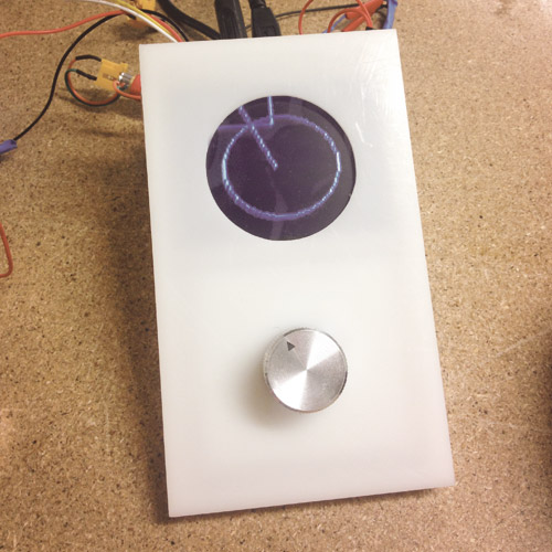
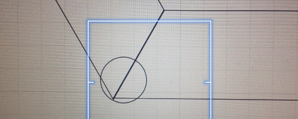
Using an Arduino UNO and the same cable, with the code here, I was able to get some snow patterns.
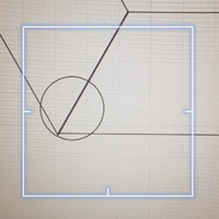
With the UNO, the cable, and the arduino-tvout library I was able to translate the potentiometer values to the size of the circle.
The relevant code is:
int analogValue = analogRead(0)/25;
TV.draw_circle(x,y,analogValue,1);
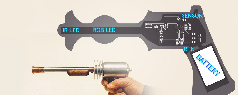
Through a conversation with some classmates, we came up with a proposal for a Raygun style game where each device has an RGB LED inside a sphere in the shaft. Each player starts with a different color, and shooting another player turns them that color.
The point of the game is to turn everyone into your color.
←
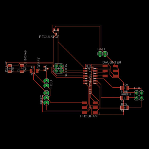
Co-designed the LAZZOR Awesome board with a classmate Justin who did the heavy Eagle lifting.
Send and Recieve IR on the left, with trigger button above. RGB "status" LED on the right side of the diagram.
We did not build this board, but Eagle file is here: LazzorAWESOME.brd
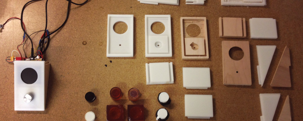
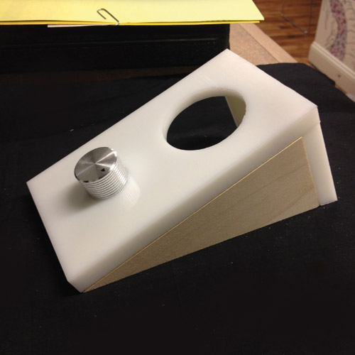
Every Curious Sound Object needs an enclosure, above are some of the experiments along the way in wood and HDPE.
←
Final iteration of the face with circular hole for screen, a snug pocket for the potentiometer, and grooves for the wall tabs.
←
The wooden sides needed tabs to fit into the face grooves, so I used the grayscape png depth capacity on the Modela, and a 1/8" bit to mill these walls. It takes a while, but comes out sharp and smooth.
←
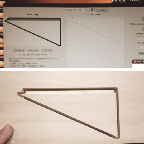
Because the rear panel doesn't meet the surface beneath at 90 degrees, I calculated the appropriate angle and milled that on the Modela as well.
←
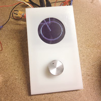
Assembled sound object with some simple geometry responding to potentiometer position.
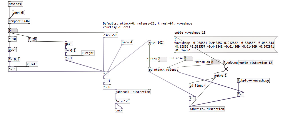
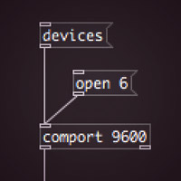
Getting serial data from Arduino to Pd is fairly easy and just requires an [open #] and [comport 9600] functions (top left) to read the value (0 in the image). This patch takes that value from an analog pin – in this case a potentiometer in the sound object knob – translates it into an audible frequency range and runs it through a distortion wavetable to create a fuzzy wobbly sound modulated by the knob.
Download Pd patch here: distortionwtimedep_01.pd
Arduino analog read / send to serial sketch here: AnalogValuetoSerial_01b.ino
The Arduino patch above takes the 0-1023 values from the potentiometer and divides it by 8 to make the values fit into the default 7bit (0-127) protocol.
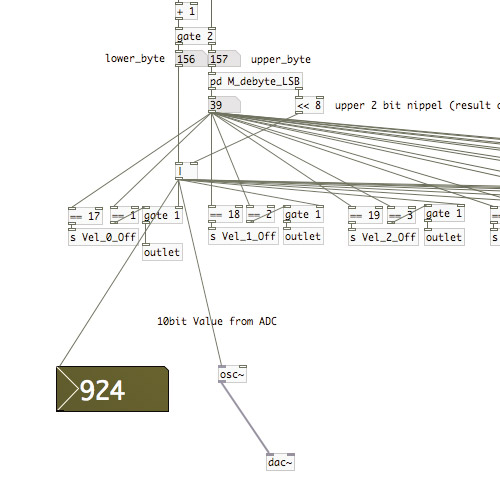
But what if we wanted to get the full 0-1023 range of the potentiometer sent to Pd. This requires a custom 10bit protocol and fortunately someone has written both the Arduino sketch and Pd patch. Download here.
←
The 924 value on the left demonstrates this protocol working within PureData. The knob is turned almost all the way to the right.
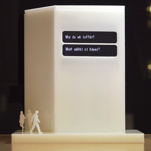
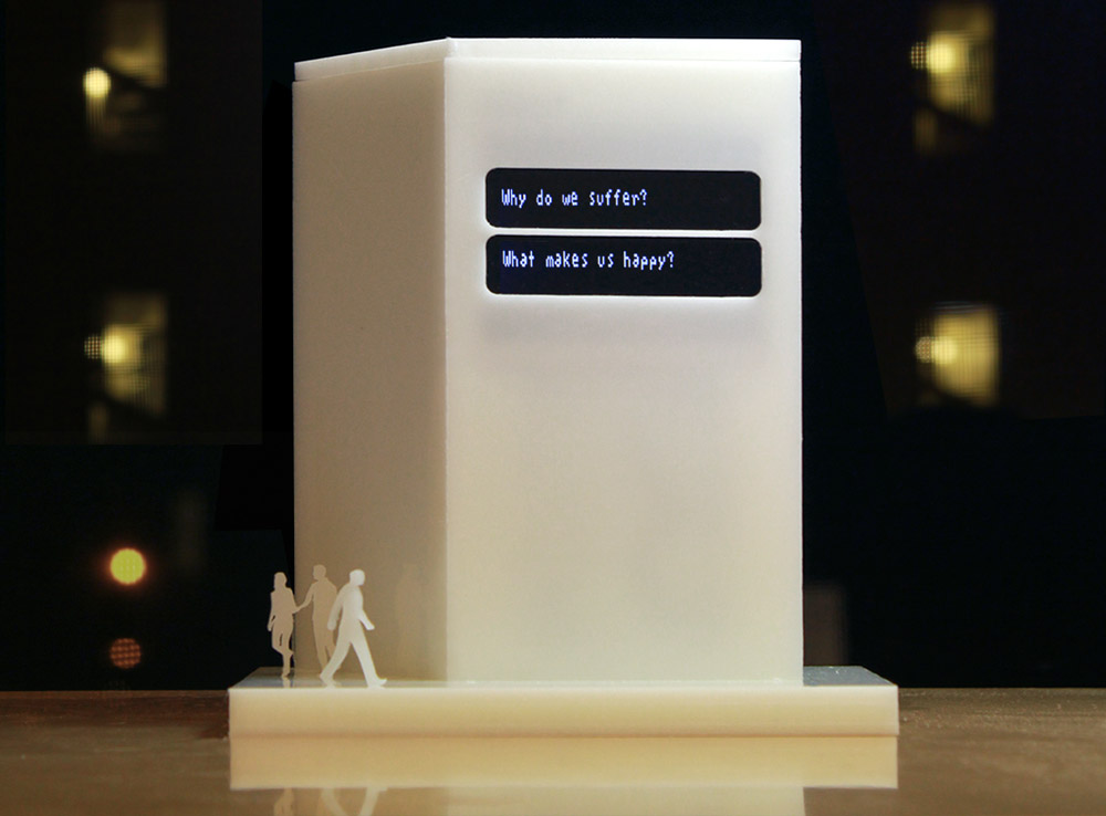
The Space Between is an art project designed to live in public space, so in order to facilitate getting funding and develop a proof of concept, I will create a small tabletop size version of the project.
←
Proposal of final installation.
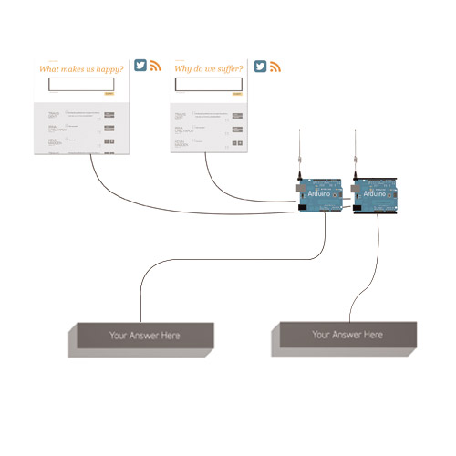
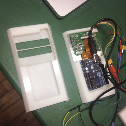
The maquette will work essentially like the final proposed project, with web forms for the questions, Python to parse the answers, and output to Arduino over serial.
Additionally I will use the Adafruit 3.5" TV ($45) as the display, and HDPE (~$20) for the shape.
The "real" version would use heavy duty LED marquees instead of the screen.
I consider both The Space Between and the Curious Sound Object to be my final projects. The former is an art project for which I hope to get funding, so I'll focus on CSO since I aim to make that a design/art object business, and there are more components involved.
Big thank you to an old friend and graphic designer Pong Ko for the logos above.
I am organizing a "Curious Sound Objects" art show at the Industry Lab Gallery Space in Cambridge, MA on Aug 2, 2014.
Check curioussoundobjects.com for details shortly.
I will display my piece along with submitted pieces.
Subsequently, I hope to turn CSO into a brand, and eventually a storefront for aural curiosities.
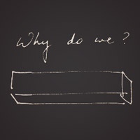
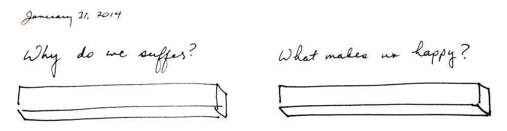
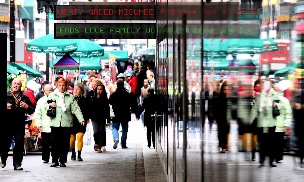
This is a proposal for a public art project where answers to two questions are projected side by side.
Input from here:
←
A Photoshop mockup of the installation on a building.
A big thanks to my old friend and AS220 classmate Gerard Patawaran for suggesting I turn the right wall inward to be parallel to the left (resulting in the parallelogram shape) and for helping me flesh out the concept over the years.
←
I constructed the outer form out of HDPE, with a groove for the walls in the base so no additional fasteners were necessary.
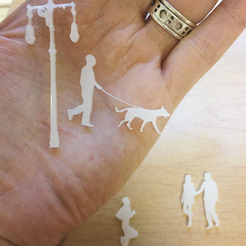
←
The people are there for scale.
I deliberated which one shape would be most approriate, since using a single person or shape potentially carried some meaning about that one shape.
Using several people instead makes it just "people."
←
Version 2 of the faceplate next to original version. The screen fits snugly and has a pocket for the screen cables. I used the 60 degree letter carving bit for the angled sides.
←
In order to alleviate the wire clutter and attempt to reduce video flicker, I fabricated this video out "half" shield (since the container holds the Arduino in place on one side and does not allow for a full shield).
Download it here:
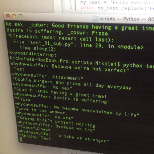
This was my first foray into Python. The forms are simplified Google Forms, which publish to Google Docs, which in turn output RSS.
I used the Feedparser library for Python to read the RSS.
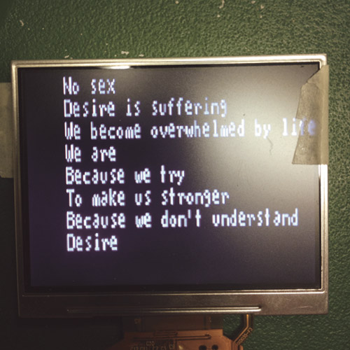
My code to read the RSS and output to serial and display can be found here:
←
Some resulting pairs.
Feel free to click on the links above and add your own answers.