This week’s assignment is to add an output device to a microcontroller board you've designed and program it to do something.
In this case this assignment has Two important Steps:
I choose to control the brightness of a Bulbe which simulates an AC motor.
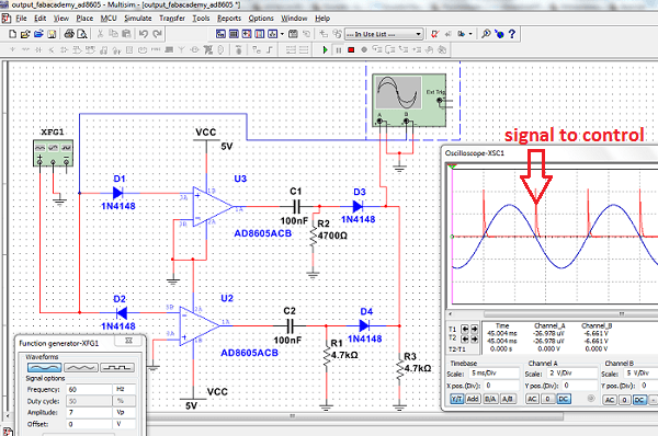
Before creating the schematic to route the board, I simulated the analogue part to see what I desired to obtain.
For this assignment, I design this schematic:
Now the description of each part:
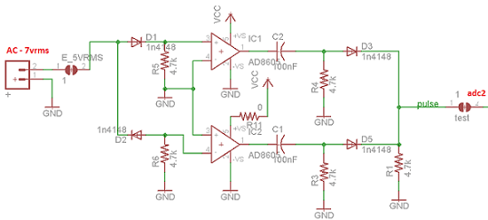
The connector has an alternating signal 7vrms (10vmax). Diode D1 lets go the positive part to the Opamp (IC1). The Opamp is working as a comparison with the GND. Here out, we will have a positive square wave. That wave will pass through the capacitor which transforms it into a pulse and reduce it with D3.
Diode D2 lets go the negative part to the Opamp (IC2). The Opamp is working as comparison with GND too, here out, we will have a positive square wave. That wave will pass through the capacitor which transforms it into a pulse and reduce it with D5.
Now, in the resistor R1 I obtain 2 pulses for Period synchronise for the input signal.
In this part, I used an Atiny44 to create my signal to control the moment that I decide to activate the bulb. For the moment, this activation depends on the number of pulses which are made by the switch (S1).
To make that, I use the Arduino IDE to create the program (output.c) to the Atiny.
In this electronic part, is important to protect the control or digital part. For that, I put an optocopler (opto-Triac) to transfer the pulse to the triac which controls the activation of the 220v (and the bulb).
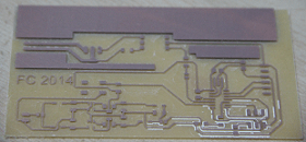
And now, the routing board..:
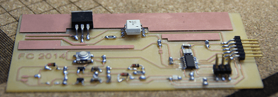
... making the board with the Roland and mounting the components ...
After that, the next Step is test and programming.
.
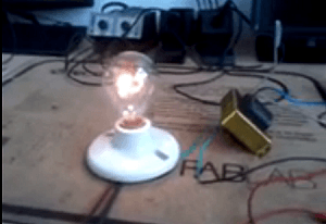
And here was the result.
click here to video
That's all ....
In this case this assignment has Two important Steps:
- Step one : Make an Electronic Board
- Step Two : Program this Board
Step 1 : Make Electronic Board
For the design of the electronic board, first I need to choose what output device to control.I choose to control the brightness of a Bulbe which simulates an AC motor.
Before creating the schematic to route the board, I simulated the analogue part to see what I desired to obtain.
For this assignment, I design this schematic:
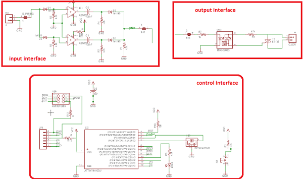
Now the description of each part:
- Part one : Input
- Part Two : Control
- Part Three : Output
Part one : Input
The connector has an alternating signal 7vrms (10vmax). Diode D1 lets go the positive part to the Opamp (IC1). The Opamp is working as a comparison with the GND. Here out, we will have a positive square wave. That wave will pass through the capacitor which transforms it into a pulse and reduce it with D3.
Diode D2 lets go the negative part to the Opamp (IC2). The Opamp is working as comparison with GND too, here out, we will have a positive square wave. That wave will pass through the capacitor which transforms it into a pulse and reduce it with D5.
Now, in the resistor R1 I obtain 2 pulses for Period synchronise for the input signal.
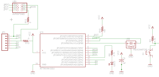
Part Two : Control
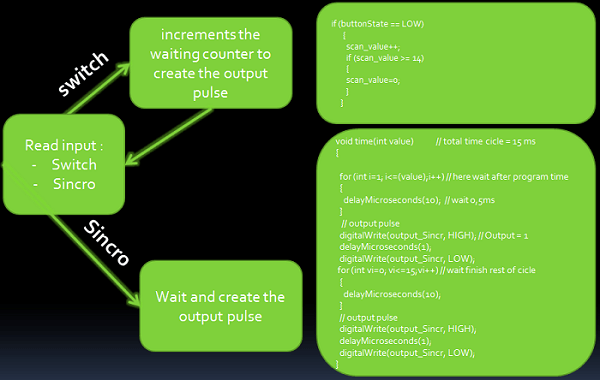
In this part, I used an Atiny44 to create my signal to control the moment that I decide to activate the bulb. For the moment, this activation depends on the number of pulses which are made by the switch (S1).
To make that, I use the Arduino IDE to create the program (output.c) to the Atiny.
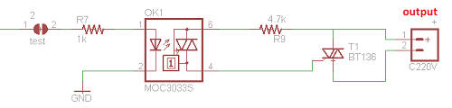
Part Three : Output
In this electronic part, is important to protect the control or digital part. For that, I put an optocopler (opto-Triac) to transfer the pulse to the triac which controls the activation of the 220v (and the bulb).
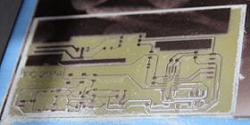
And now, the routing board..:
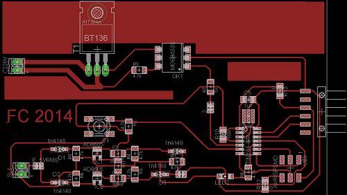
... making the board with the Roland and mounting the components ...
After that, the next Step is test and programming.
Step 2 : Programming Board
Now, the Hardware was finished, it's necesary to program it..
And here was the result.
click here to video
That's all ....