This week’s assignment is design and build a wired &/or wireless network connecting at least two nodes
In my case, I decide to Fabacademy Network boards, Hello.bus.45.bridge and hello.bus.45.node, to make a RS232 Network intercropped in which two electronic cards to send the information to light. For that I create 2 new boards.
For that, all the project was divise in 3 parts:
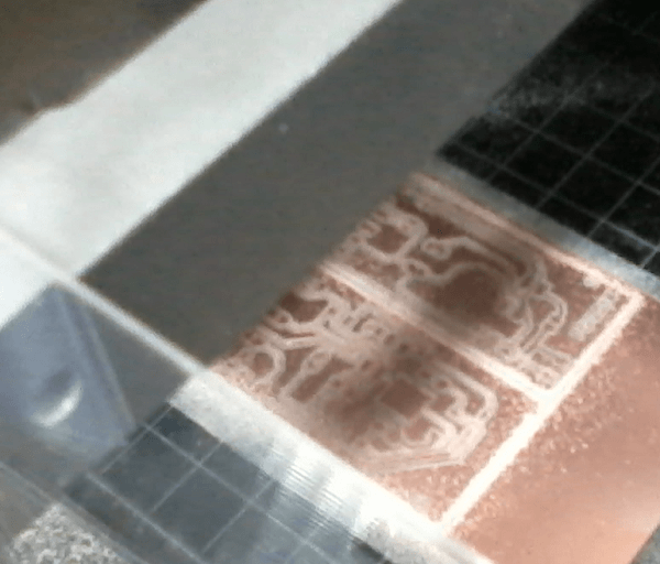
All this boards was made with the "Modela" and month with the Fablab components.
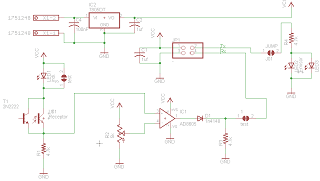
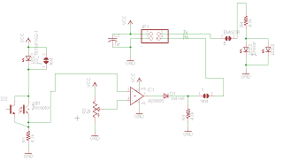
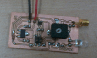
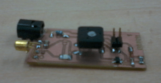
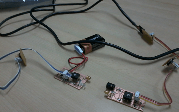
For this electronic boards, I need a light emitter (LED High Brightness, I use a Mouse led) for the emitting parts, and a photo-transistor for receive light and an amplifier for amplifying this signal.
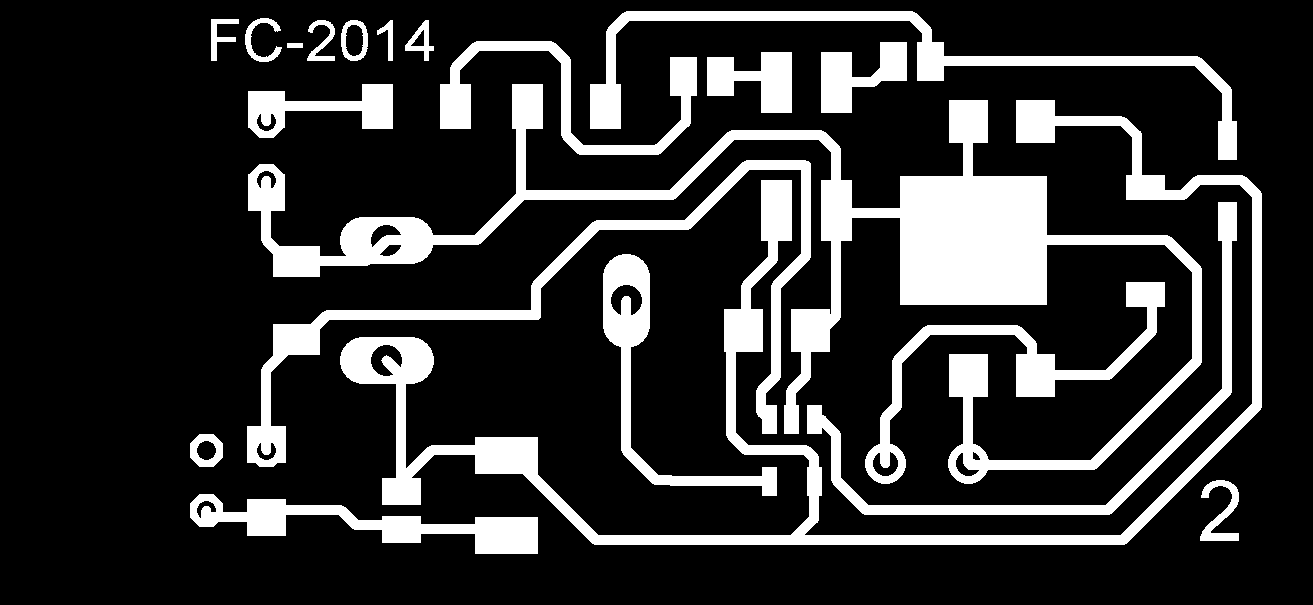
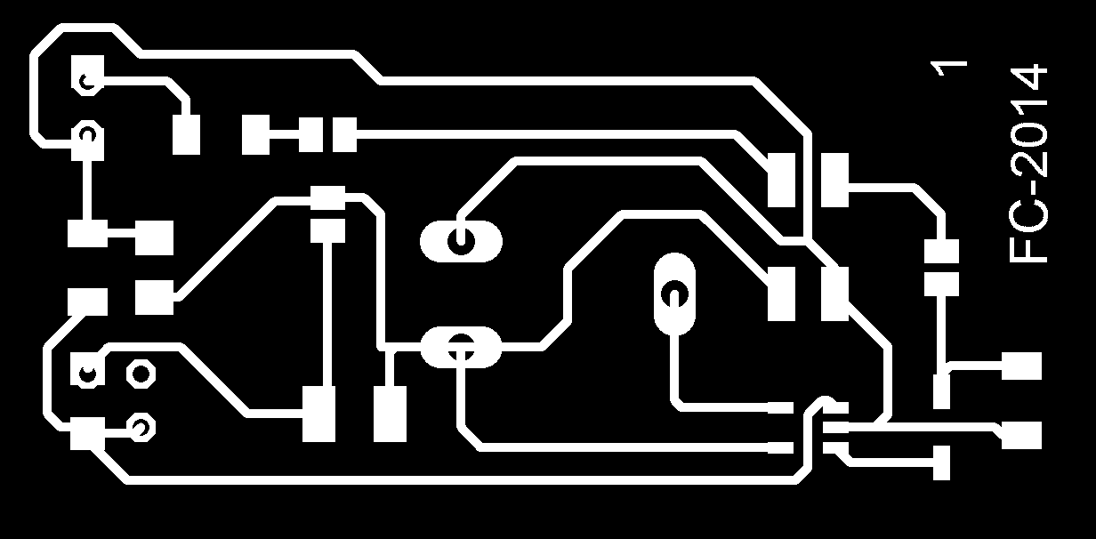
The difference between the 2 cards is that one needs a external power (9V battery - Board 2) with a 5v regulator, and the other feeds the power supply to the network cable (board 1).
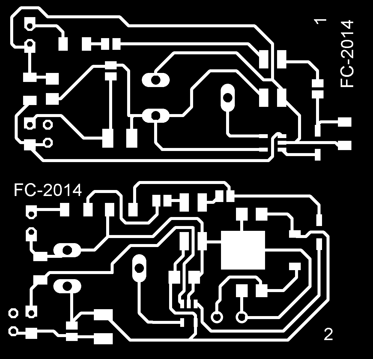
To optimize the use of the roland, and the space on the card, I put the 2 cards in a single file.
And after that, mount the component in the boards.
When all the cards are ready, program them.The unique cards that I have set are the Fabacademy (bridge and Node), the other 2 only serve as interface.
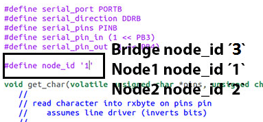
I downloaded and modified the C code. Each board ( bridge and nodes) needs to have a different ID number. We therefore need to change the line below in the hello.bus.45.c code. In my case, I defined the bridge as '3', one node as '1', and another node as '2'.
#define node_id '1'
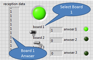
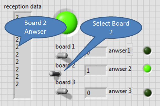
Once the boards are flashed, we can communicate with the network using a Labview interface.
When I push the switch, the LEDs on all the boards lighted up once, and the LED on the board with the number I typed lighted up again.
Then, I connected the FTDI header to the bridge boards, and made the serial connection between the boards with a 4-pin serial cable.
Try to connect ..
And here was the result.
click here to view the video
That's all ....
In my case, I decide to Fabacademy Network boards, Hello.bus.45.bridge and hello.bus.45.node, to make a RS232 Network intercropped in which two electronic cards to send the information to light. For that I create 2 new boards.
For that, all the project was divise in 3 parts:
- Part one : Make Fabacademy electronic Boards
- Part two : Make my optical adapter
- Part three : Program the Boards
Part 1 : Make Electronic Boards
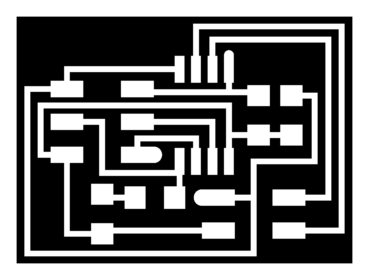
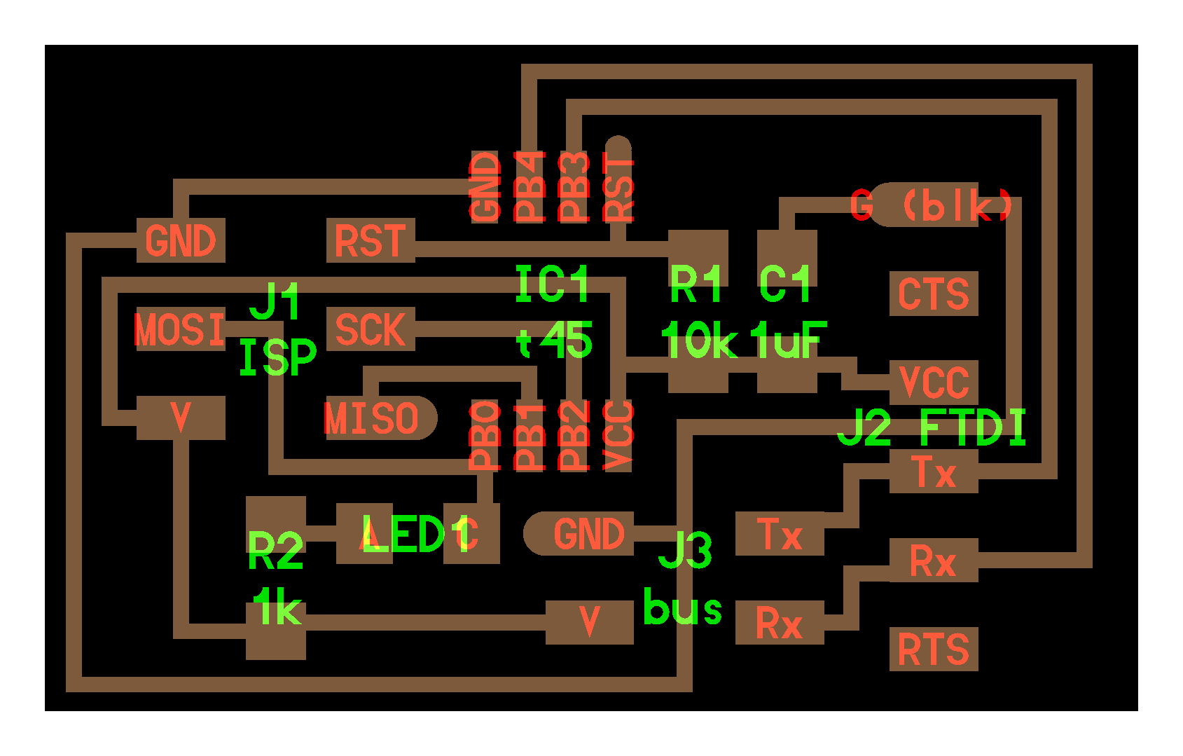
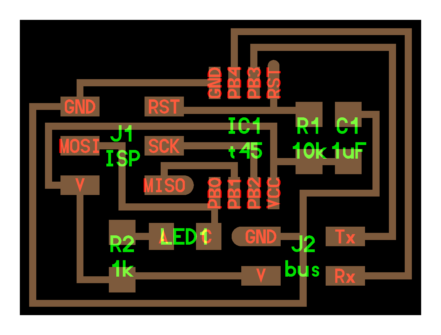
For the network electronic board, I choose to use first, the "hello.bus.45.bridge" board to receive the data to the computer and two "hello.bus.45.node" board to receive data and put "ON" the integrate led.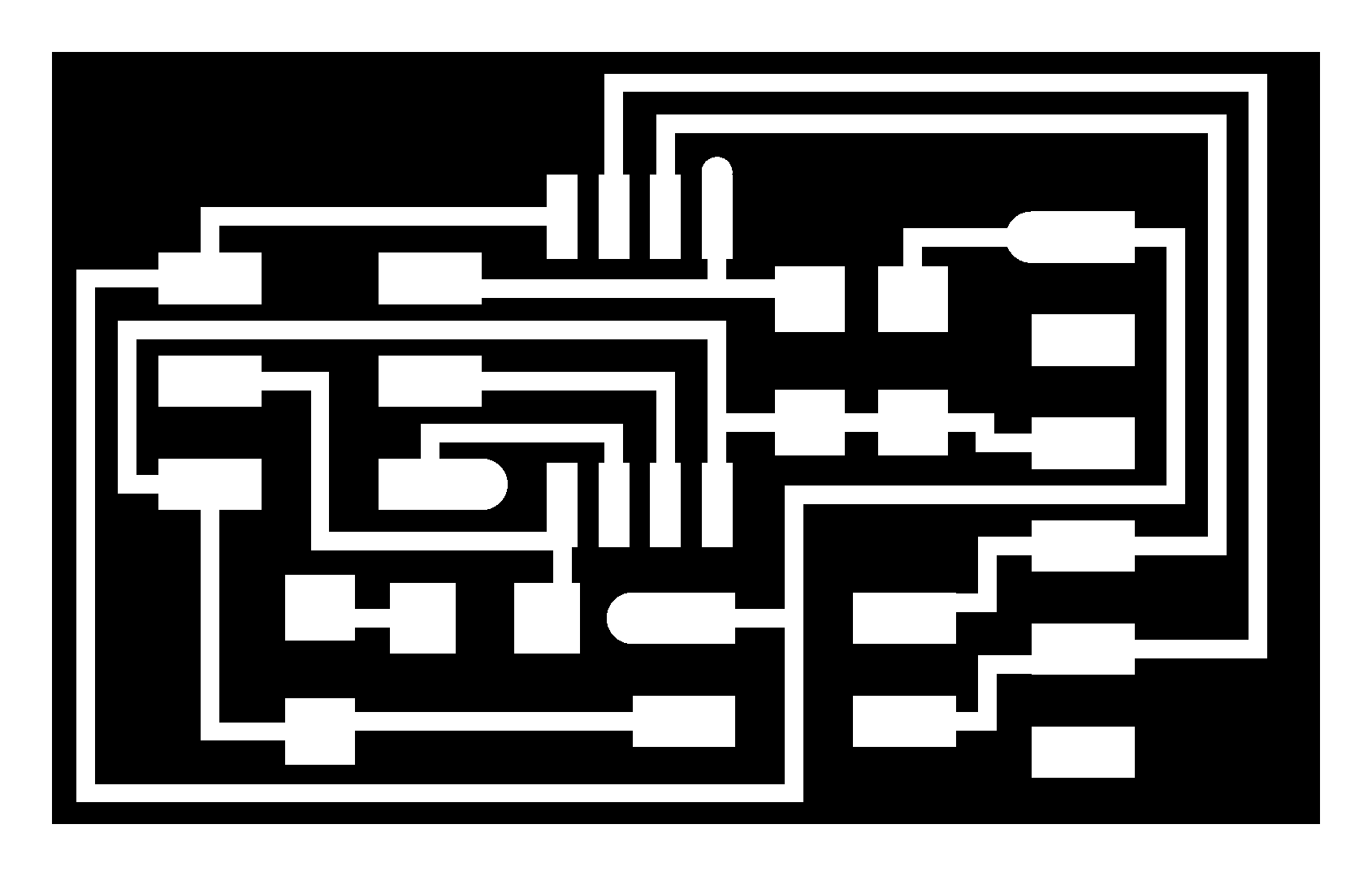
All this boards was made with the "Modela" and month with the Fablab components.
Part 2 : Make my optical adapter
For this electronic boards, I need a light emitter (LED High Brightness, I use a Mouse led) for the emitting parts, and a photo-transistor for receive light and an amplifier for amplifying this signal.
The difference between the 2 cards is that one needs a external power (9V battery - Board 2) with a 5v regulator, and the other feeds the power supply to the network cable (board 1).
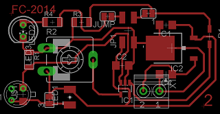
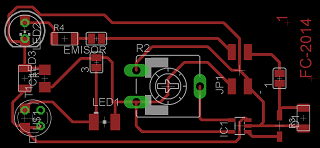
To optimize the use of the roland, and the space on the card, I put the 2 cards in a single file.
And after that, mount the component in the boards.
Part 3 : Program the Boards
When all the cards are ready, program them.The unique cards that I have set are the Fabacademy (bridge and Node), the other 2 only serve as interface.
I downloaded and modified the C code. Each board ( bridge and nodes) needs to have a different ID number. We therefore need to change the line below in the hello.bus.45.c code. In my case, I defined the bridge as '3', one node as '1', and another node as '2'.
#define node_id '1'
Once the boards are flashed, we can communicate with the network using a Labview interface.
Try to connect ..
click here to view the video
That's all ....