Now,submit the final project.
The first question was :
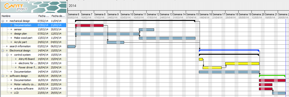
What tasks have been completed, and what tasks remain?
According with what was planned I have completed 3/4 of it.
The tasks to be completed are:
- Design and construction of the Hub Wind (Completed)
- Design and construction of the Test zone (Completed)
- Design and construction of the Wind expansion zone (Completed)
- Design and manufacture of electronic circuits (Completed)
- Ensamble all the mechanical structure with electronic (in progress)
- Test all the wind tunnel (in progress)
But First, the most important Question :
What will it do ?
My project is to design and manufacture a wind tunnel.
But before to speak, an important question is:
what is it?
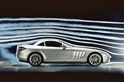
Let's start by defining wind tunnel : It is a tool that allows us to study the behavior of air when we put an object in the flow. That object can be anything: a building, a Formula 1 car, a helmet, a cyclist, and so on.
we must consider that the size of the model will influence the test results. The larger the model and the closer to reality, the better the test results.
This allows us to study the relative motion between the object and the air.
Now that we know is a wind tunnel, you have to find out more about how it works, you have to have shapes to work well.
That I found this books:
- WIND TUNNELS AERODYNAMICS - ISBN: 978-1-61209-204-1 - Nova science publisher edit. chap07
- Wind Tunnel designs and their diverse engineering applications - edited by N.A. Ahmed
Now we have to see section compose the tunnel
Tunnel description

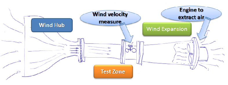
If you look the tunnel, you observe 3 diferents mechanical forms:
- the wind Hub (or inlet contraction)
- the test Zone
- the wind expansion zone
And 2 parts who need electronics:
- Wind velocity measure
- Wind extract zone
And I need to design all of this diferents parts.
I decide to begin for the mechanical zone, for me the most complicate parts.
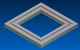
WIND HUB
Wind hub.... the most complicate part of the tunnel... But why is it so complicate ????
because its shape allows air to exit parallel to the test area.
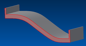
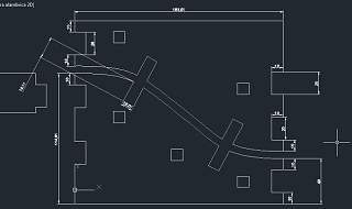
The shape is represented by a mathematical equation of 5th grade:
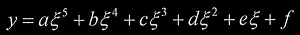
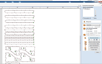
After resolution of the equation I put them in Excel to calculate all the point that I need to obtain the shape.
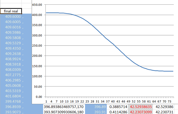
Now I need to copy the Excel result in Autocad to design the exact form. For that I create a new Column to put my result.You copy this column with the result.
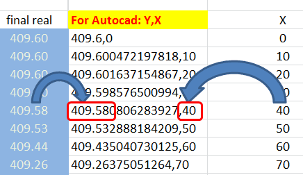
And Open Autocad, select Polyline, put the first point and paste the select excel column.
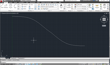
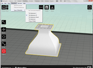
When you take this form, you export them to use in inventor to design the 3D form.
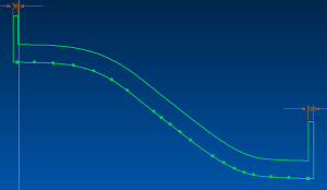
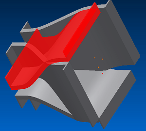
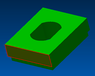
After design the shape, I print them with the 3D touch and the Replicator 2X
Now, the nozzle design was finished, and I need to make them.
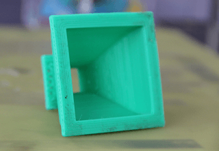
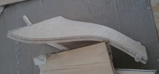
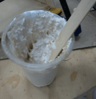
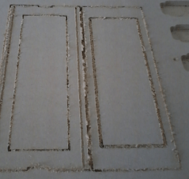
I need to create the exact form.... for that I decide to create a composite material (look Composite assigment) and mold them with the mold that I create.
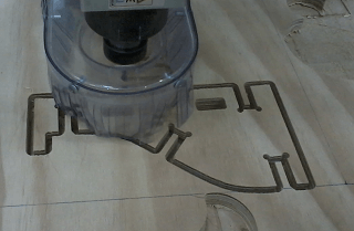
As the hub has 4 faces is required manufacture 4 parts in composites material.
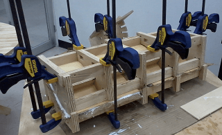
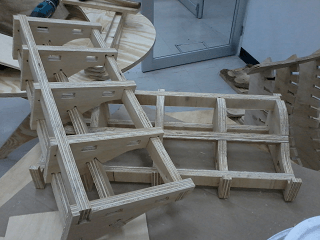
Since I have manufactured my 4 pieces, I can begin to unite them and form my hub.
After a drying time of 3 days, are demolded and cut necessary to mount.
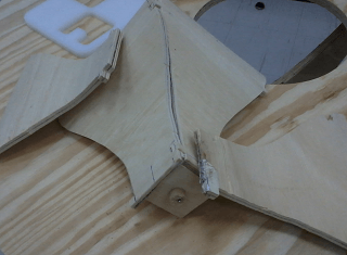
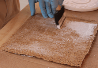
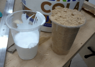
already mounted, but now lack cover all openings so that air does not escape for that I create my own sealant adhesive based on white glue and serine.
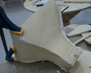
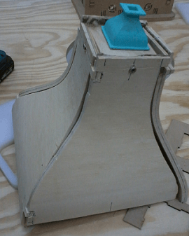
After a drying time of 2 days, the wind Hub (inlet contraction, or nozzle) was finished.
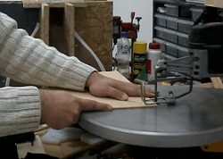
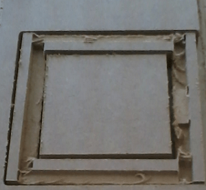
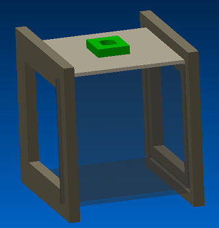
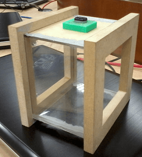
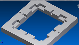
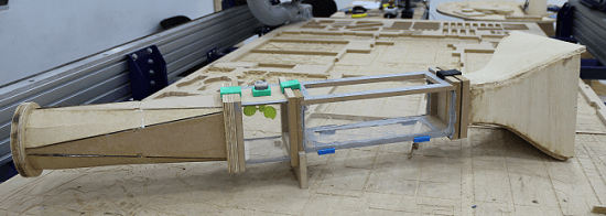
TEST ZONE
In the Test Zone becomes the object you want to analyze. So that part has a predominance transparencies, in our case, I used transparent acrylic.
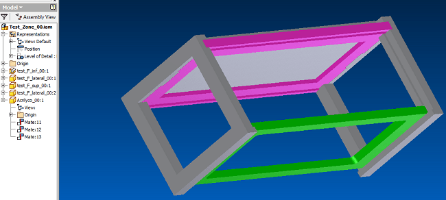
The test Zone was divise in 2 parts:
The First Parts is used to put the object that you can analyze.
And it was made with 4 MDF parts:
- 2- Lateral parts - 9mm MDF
- 2- Central parts - 9mm MDF
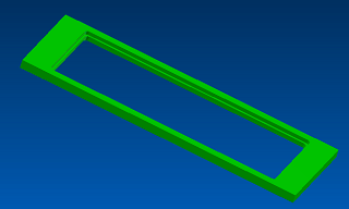
Lateral parts(Test_L00)
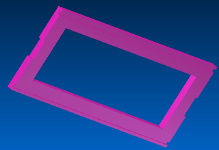
Central parts (Test_L001)
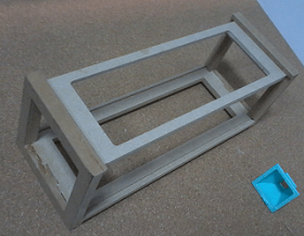
Other parts were in 3mm acrylic parts to easily add different objects to try.
The measure part was create to put the anenometer (velocity sensor).

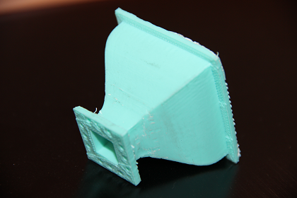
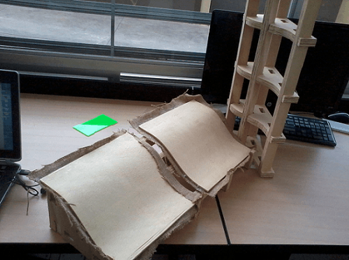
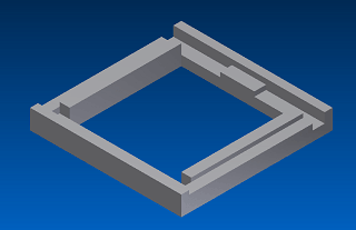
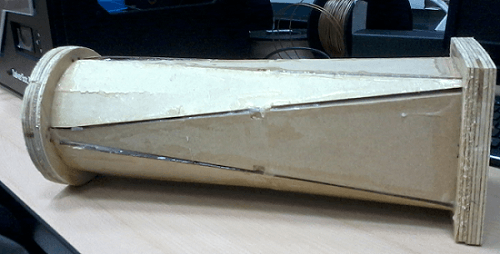
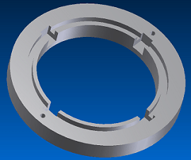
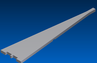
And now, the last mechanical part of the tunnel... the wind expansion zone.
wind expansion zone
Area expansion is necessary for the air circulating in the tunnel not present perturbations to the exit of the tunnel.
It goes from a square area to a circular area.
And the design of them.
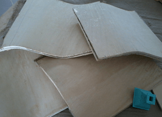
I started by designing 2 tips to do, and after the middle into 2 pieces.
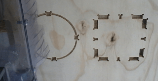
After this design, the last parts:
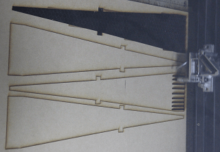
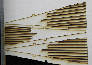
After the cut, you can turn them and put in the circle..
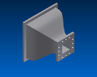
With that you finished all the mechanical parts of the tunel and you obtain:
They use diferent types of material for each part of the project.
For mechanical structure:
- Plywood
- Acrylic
- MDF
- Material for finishing
All of this materials are purchased locally.
Electronics Parts
I need diferent board :
- Electronic sens Wind velocity
- Electronic to control Wind extract
Sense Wind velocity - wind extractor
For this part, I make my sensor of wind velocity in
Input assigment .
In the assigment, I create all the amplification system, and the design of mechanics.
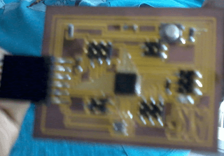
But I note that also needed to use an output to control the speed of my engine to draw air from the tunnel. That's why I decided to create a new card that integrates meter of air speed ( anenometer) and control the speed of a DC motor with power interface.
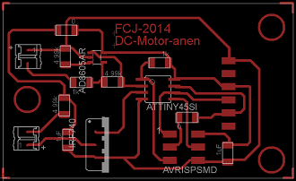
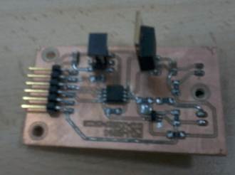
And to control this velocity, I put a Atiny45 to control all with a serial conection.
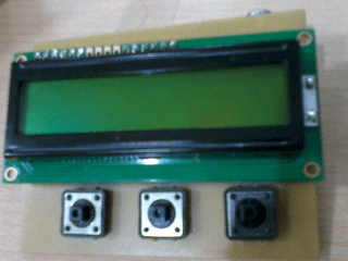
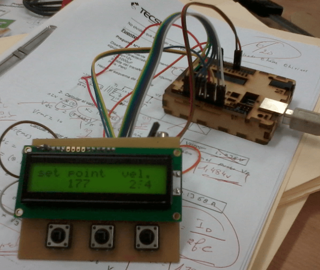
To send the data, I create another board.A board who have a 2x16 LCD screen, with a interactive menu to control speed, using a three buttons.
And for control all of that I used a Fabduino for the flexibility to program (click to read the program) . Yes, I work first to the arduino to make and test my interactive menu and after I remplace the arduino with my Fabduino.
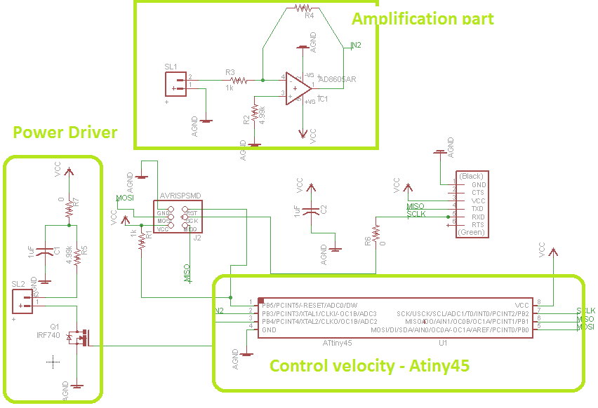
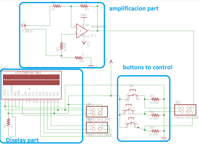
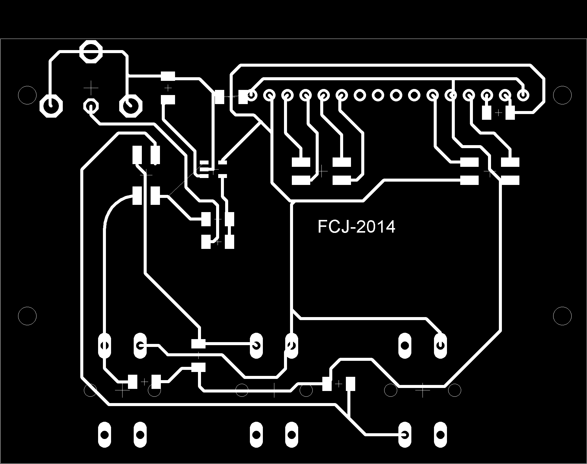
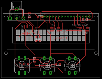
electronic wiring diagram
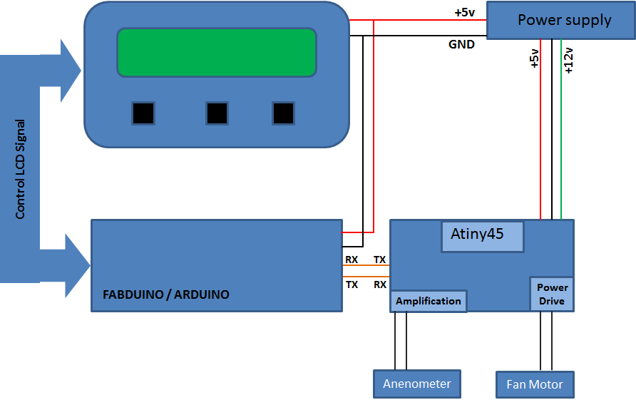
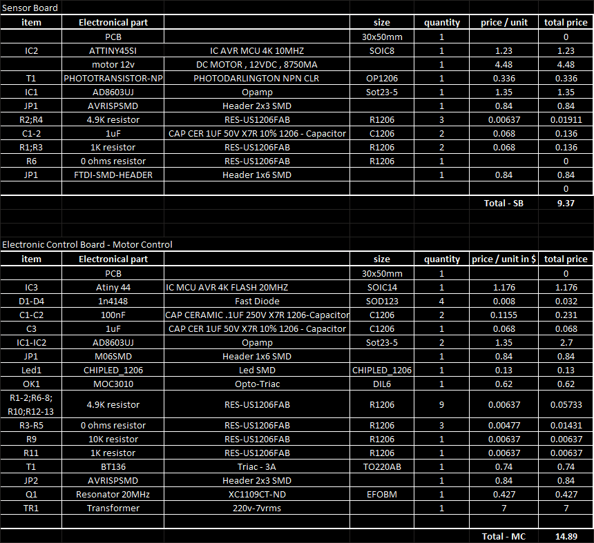
The most important components of the electronics parts are:
- Atiny45
- AD8603UJ (opamp)
- IRF730 - power driver for DC motor
- Resistors, capacitors ...
Where will they come from ?
I found the plywood, MDF, and Acrylic at a local shop.
About the electronics, most of the devices are available at FabLab, and the others can be found in electronics local shop.
how much will it cost ?
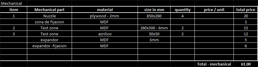
The most expensive part is the mechanical parts.
Electronic parts
From the white glue and sereine, to make windproof the hub, it's not easy to evaluate the real cost, because I used a little of each one.
Another cost that is dificult to evaluate is the motor because I use one from a damaged server.
What parts and systems will be made?
I’m going to make all mechanical parts using the shopbot and making composite material for Hub parts and for the expand parts. They are made of wood.
For the central parts, I will make them using MDF and acrilyc.
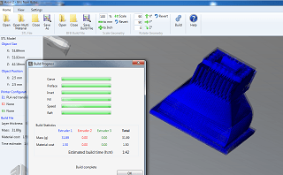
The mechanical part of the anemeter is made ( or impress) with the Replicador 2X.
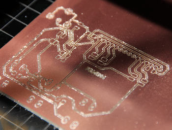
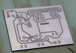
For the electronics Boards (sensor and control), I make all of them in the fablab.
What processes will be used ?
For the mechanical parts:
- shopbot 2d milling ( to make expansion part)
- Epilog laser (to make test zone)
- cutter
- sanding and finishing
- replicator 2X (to sensor)
For the electronics boards and connections:
- Roland Modela mdx-20 milling
What tasks need to be completed?
- integrate electronics boards with mechanics parts
- finish to write application program
- Finish it
What questions need to be answered ?
- How can I choose the motor to obtain the wind in my tunnel?
- How can I calibrate the wind velocity measure?
What is the schedule ?
How will it be evaluated ?
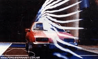
How will the wind tunnel be evaluated ? Good question.
.. putting a toy car in the tunnel to simulate a real car, and look at the smoke movement.
A question that one can ask is: the tunnel works?
In my case I was doing tests and did not work ... no smoke via lines parallel alright ... did not understand why until .... I remembered all my calculations on how air hub were to call at real size, but after the re-scale to a quarter rather than redo the calculations, is one of the possibilities that not works correctly.
That's all .... not completly ...
All files of the project are put in a Dropbox with direccion is :
DropBOX Academy 2014 Project
 Fab Academy 2014
: Final Project
Fab Academy 2014
: Final Project