Input Devices
This week assignment was to create an input device, read its data as well as visualizing it.
I was very curious about the visualization parts, so I concentrated on this part, thinking that later on I will get to create my own board as well, but the modifying of colors and shapes carried me away, and yet I have to complete this part.
I had a photocell sensor which connected to the bread board and then by three wires connected the bread board to the GND, 5V and A0 analog of the ArduinoUno board.
This tutorial was quite helpful in order to figure out the way they should be connected
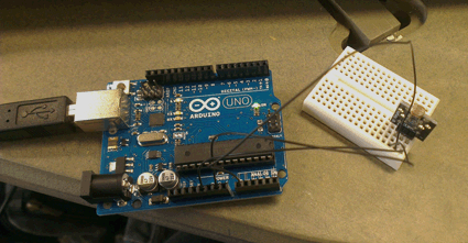
I used this code to read the sensor data:
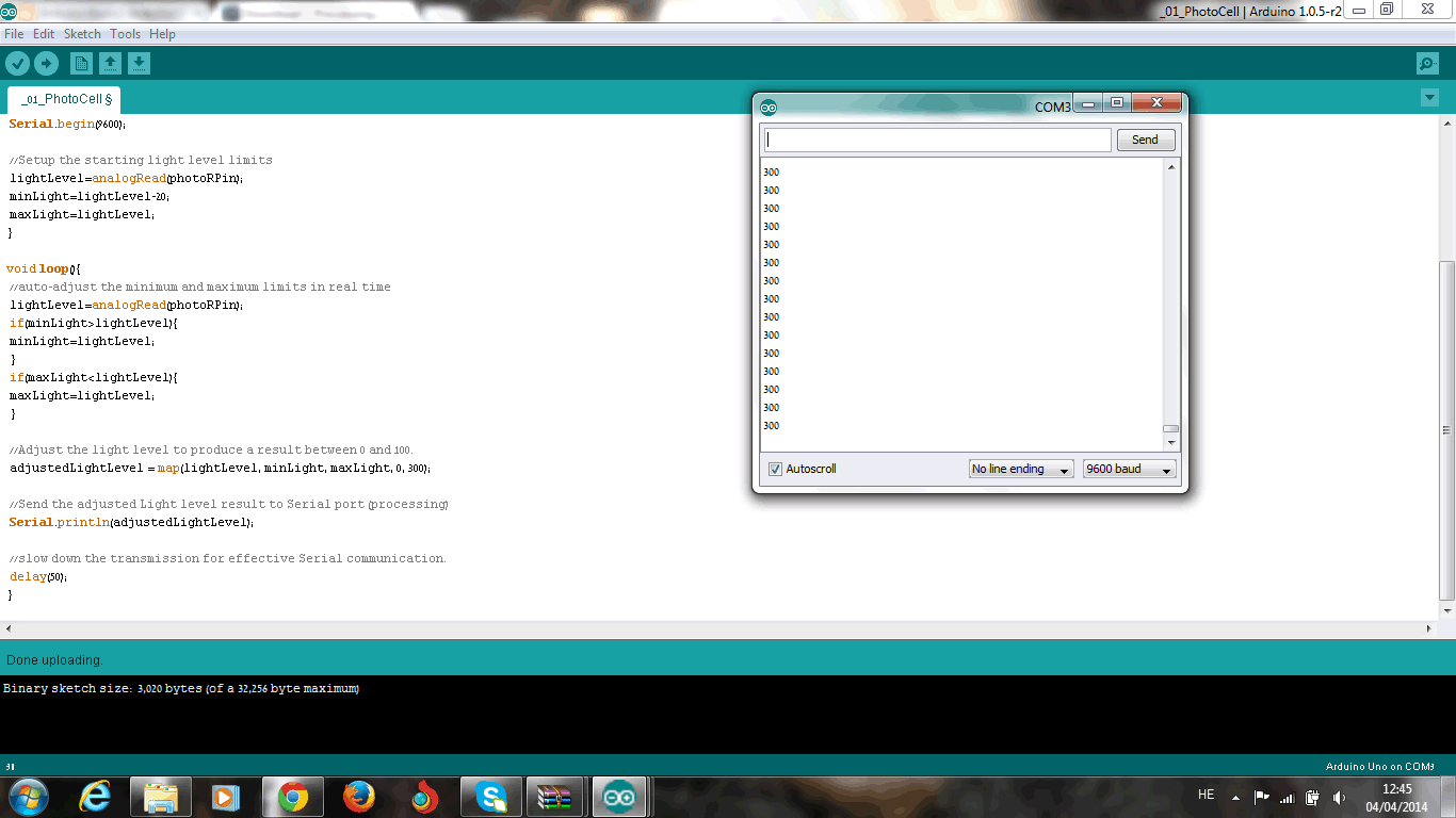
I have tested reaction in various light conditions which were translated into various numbers.
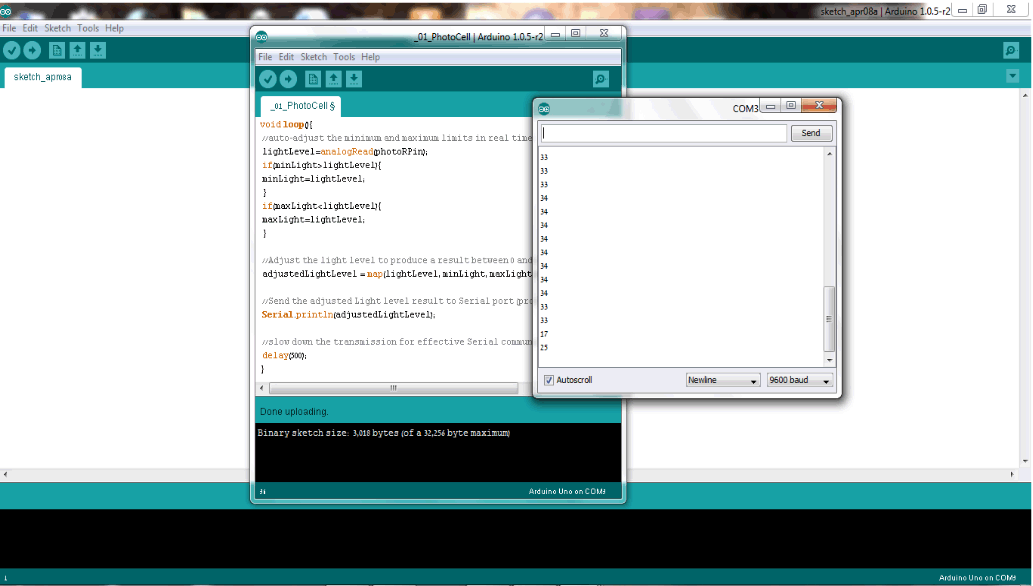
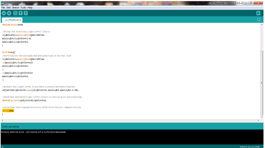
I have tried to modify the delay and ligth levels values as well
as I have already mentioned I was much more curios to learn how to visualize those datas
I worked with Processing
At first I had learn its basics, so I followed parts of this tutorial
Next step was trying modifying a code by my self.
In the Arduino libraries-communication -serial I have found this code:
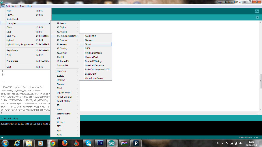
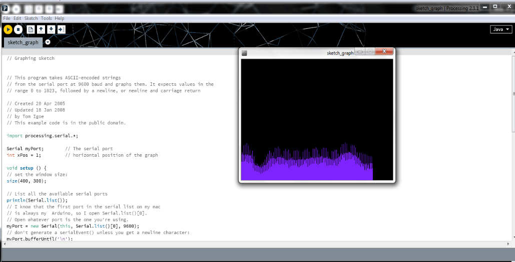
I imported it to the processing and received this graph:
Then I have tried to modify it.
At first I have received this ellipse, which could grow bigger according to light levels:
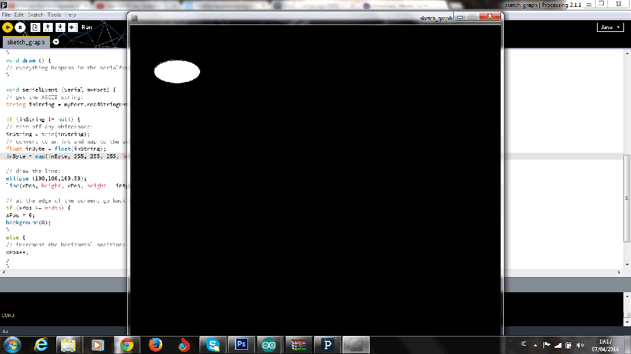
Sticking to the Ellipse idea I have changed its color and placed it in the screen center, by modifying the ellipse valuese to numbers insteade of positions, as it was in the graph code.
I have covered and reviled the sensor, in order to get more interesting results:
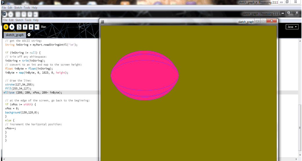
Then I have tried to combine the linear idea of the graph and combine it with the growing up and down loops, and this is what I got:
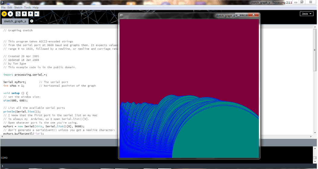
Background become green as far as eliipses reach the edge of th screen:
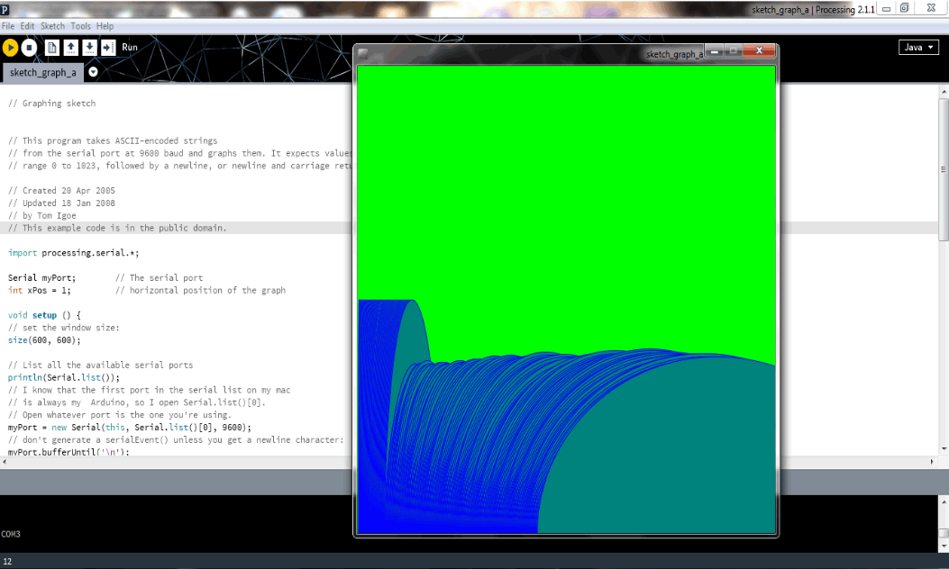
I made most of the work during day time in well lightened room, it was interesting to see it reaction in dark hours with only lamp light:
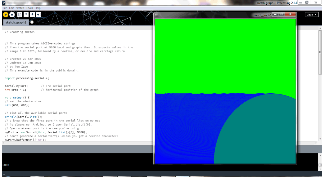
I have tried to replace the ellipses with rectangle as well:
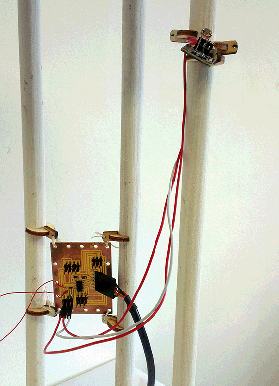
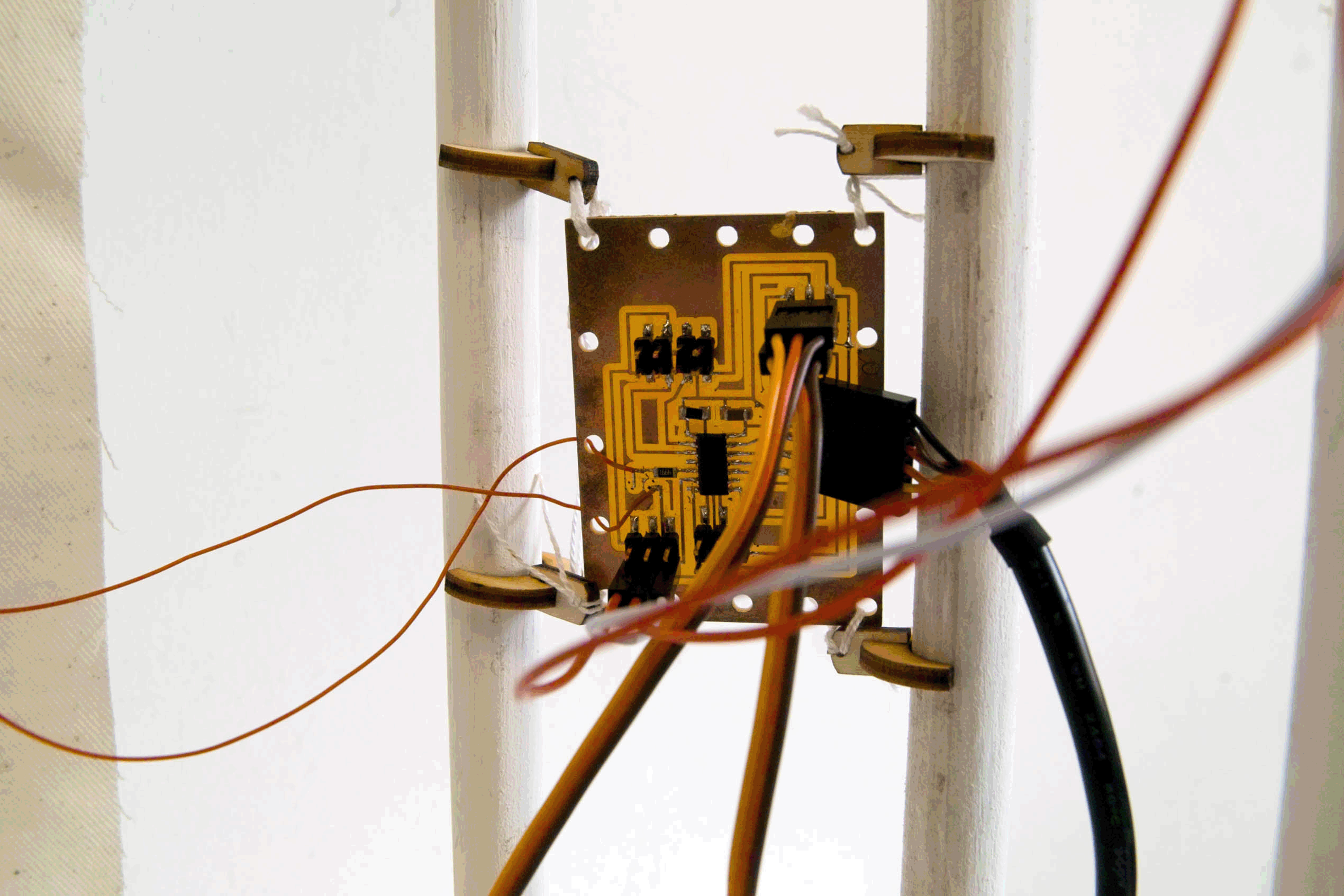
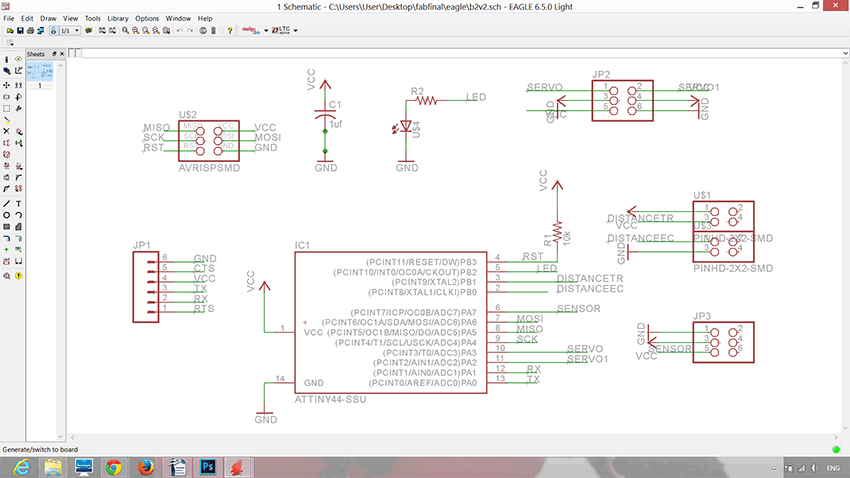
As this part of the assignment was done, I have designed my own board with a photocell, which I used in my final project as well
*
Using eagle I designed the board
*
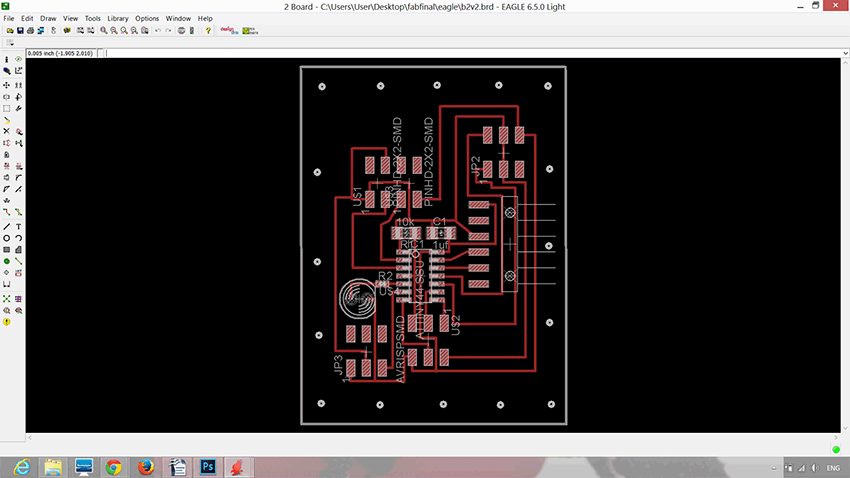
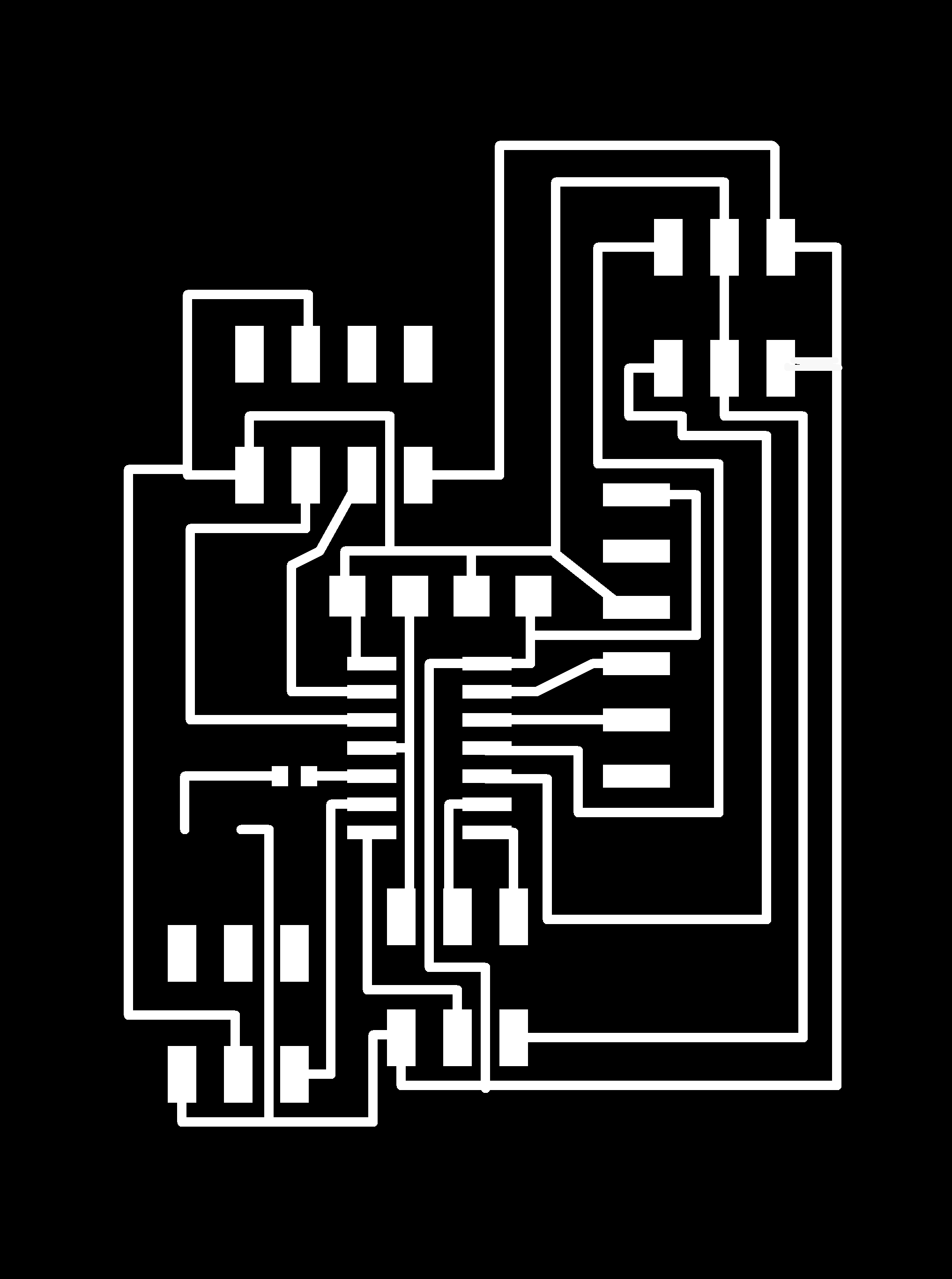
Exported the traces and interior:
*

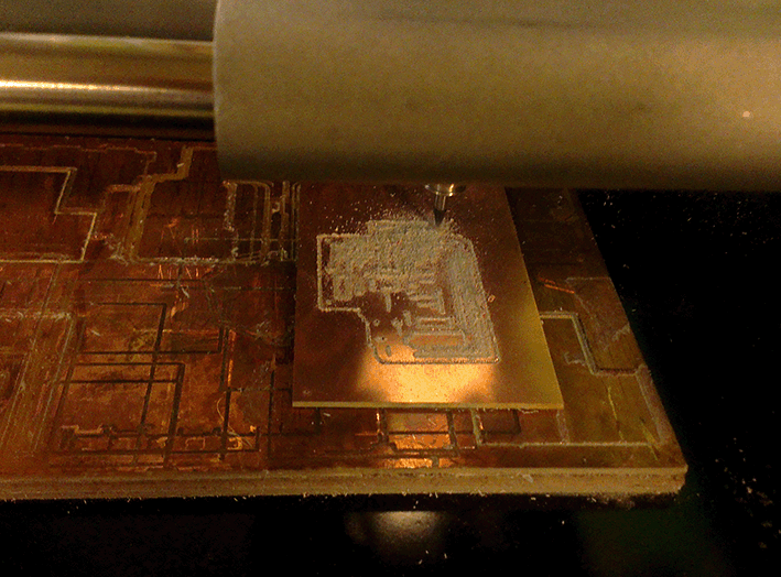
Milled:
After soldering tested it with some output device (a servo motor in a crochet doll):