Electronic Design
This week assignment was to design your own electric board,
I used Eagle, software to place of the components on the board, and photoshop to design the board frame.
It was my first time to work with eagle, and I followedthis tutorial in order to learn, how to insert, connect and place the components as well as how to design the board layout.
At first I downloaded the Hello Echo schematic and board files, as well as specific libraries of components, required for this assignment.
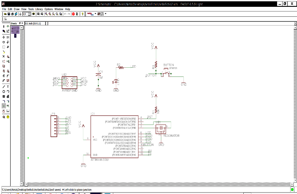
Next step was to add the following components to the schematic:
Resistor (value 10k)
Button (OMERON switch)
Ground
vcc
connect pin 10
LED
Resistor (value 499 ohms)
I connected them on the schematic:
I switched the screen into the board design screen:
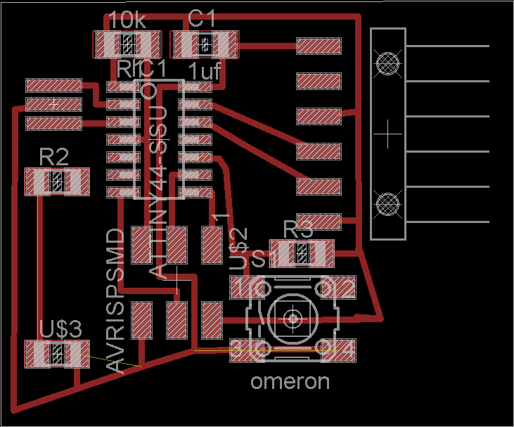
I replaced some of the components in order to get an interesting board design; it was long trial and error process, till I figured out how to get the design I wished and keep all the required connections between the components.
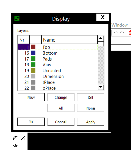
Than I exported it as a png file, in order to do so I choose only the top layer, it is important to remember this step, otherwise the file will be exported along with the text.
This is the layout I got:
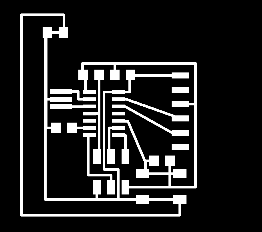
I opened the png. File in Photoshop and start the fun part of the assignment: design the board shape.
I already knew that the board will get an animal shape, so in advanced I placed the led in some distance from rest of the components, I wished the led will be the animal eye.
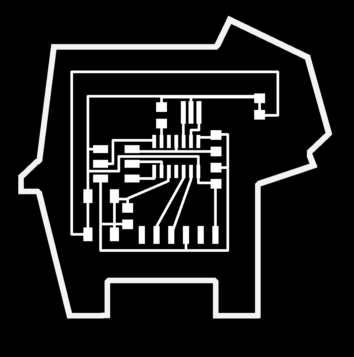
I separated the frame into new file
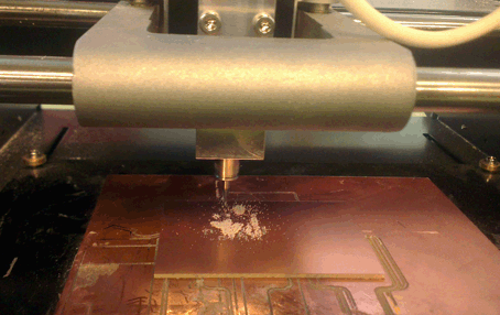
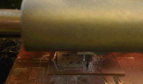
I sent the boardlayout to milling machine:
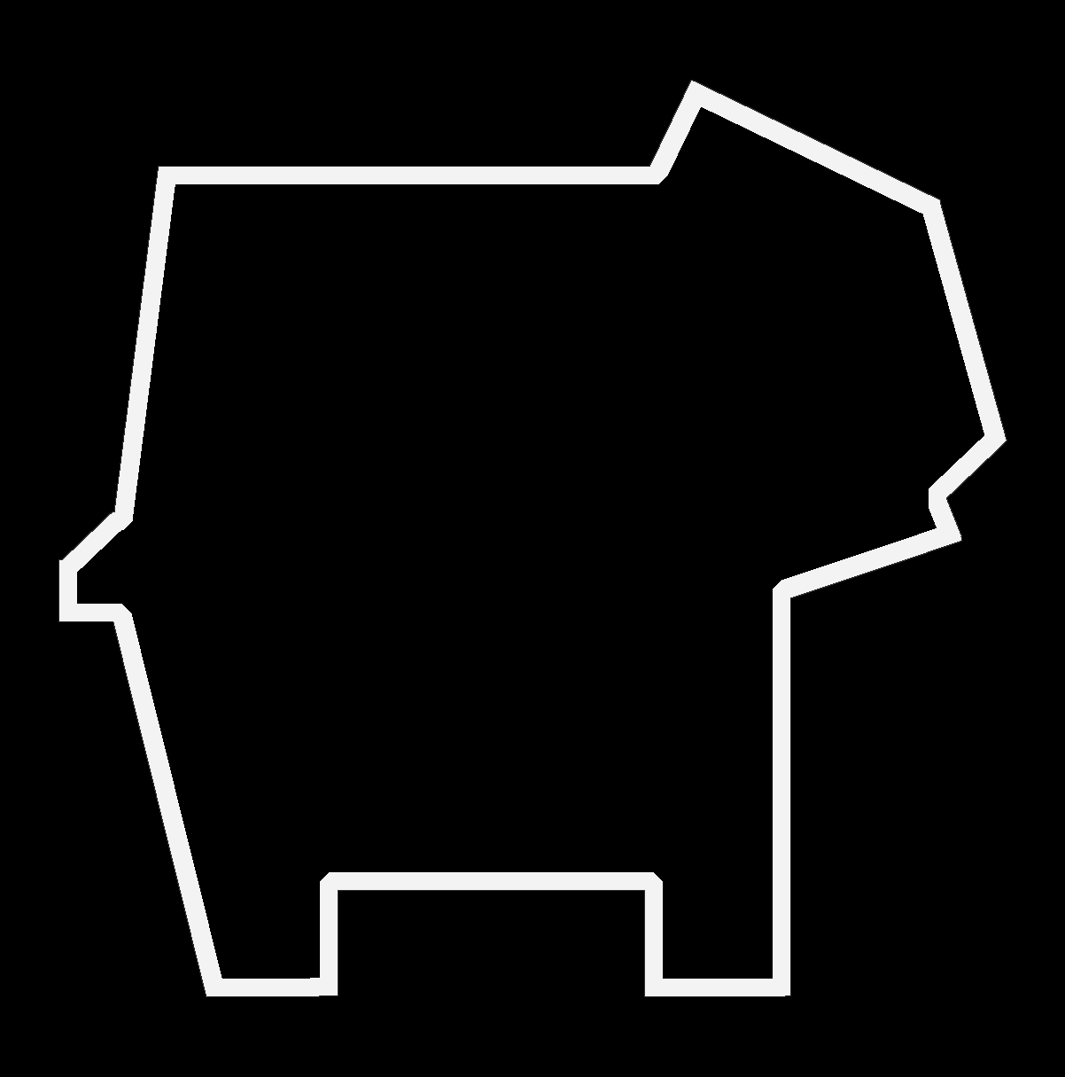
Then loaded the frame file
I soldered all the components,
Actually after this process was done I found out that I had a mistake with the board design which created a Short circuit where the button should be installed and I had to re designed the layout
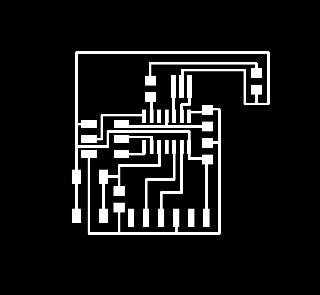
There was a problem with the milling of the frame as well, beacouse when you leave the interior of the frame black with white contour the modela mill two lines, so I fixed it as well:

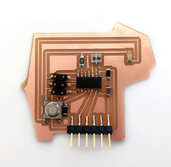
I milled and soldered new board, and this is what I got:
This is what I got:
