Electronic Production
This week assignment was creating a fabisp (an in-system programmer for AVR micro controllers)
At first I downloaded the the png File from this tuturial.
I used a "FabModules" to convert png File into G.code or rml files that can be read by the milling machines.
Then I converted it into rml, which can be read by the Modela (small cnc machine)

There was problem with the connection between the modela and the fabmodules, so we used the "Shareline 5410" machine. By fabmoduls I converted the png into g-code,and generated the path for the machine.

*
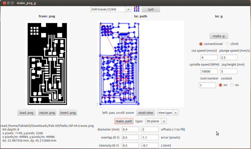
It is necessary to test path data as well. At first I tested it with path offset 2, but it didnt work well, so I gave it another try with offset 1 which was much better.
The software for milling is EMC cnc linux.
First I inserted 1/64 bit, and reset the x and y axis by placing the bit above the corner of the board and press home in the software. The Z axis should be reset as well, by placing the bit on the top of the board, and pressing home once again.
Next step was to set the milling speed; at first we used data from last year local fab acdemy student:
Feed Overrlede: 69%
Jog speed:164 mm/min
Max velocity:164 mm/min
It didn’ worked well so we slower the miling speed into:
Feed Overrlede: 50%
Jog speed:134 mm/min
Max velocity:134 mm/min
It worked better with the new speed data , and the boards seemed much better, at least at first glance:
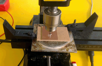
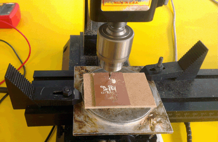
Next step was to opreate the machine:
*
*
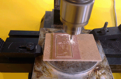
I could follow the milling process on the screen as well, it marked the already milled lines in red and in white the line which it yet have to mill.
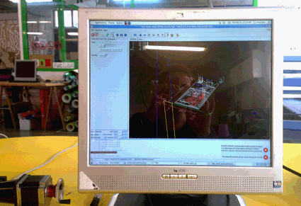
The milling of the fabisp board has two steps, first you mill the traces inside the board (which is very dlicate) and then you mill the frame.
It is two different file which should be switched when it finish to mill the traces inside.
Milling the frame is much easier and faster, and can be done by bigger mill (1/32) and maximum speed data.
By the end of the two process I recived the board:
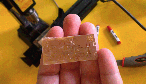
Next step was to solder electronic components on its top.
I used this tutorial, which give all the instruction about the soldering work flow .
As it is my first time to deal with this kind of work I wasn’t aware for some details, and I faced a problem with the boards itself, one of the line were missed and I had to complete it using a bridge-Soldering another piece of wire, between two points in order to keep the connections. Actually it would have been better to mill another board with slower milling speed, and avoid those kind of improvisations.
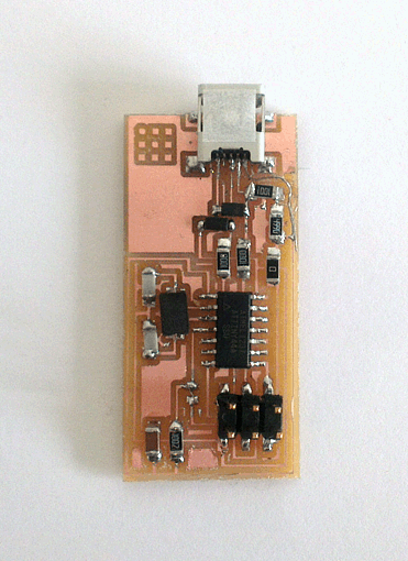
Programing
First I downloaded the AVR programing software, from this tutorial
I connected the FABISP to the AVR programer
first I got the orange light few times, it was result of mistakes with soldering, which I had to re-solder
Finally I got the green light- sign that everything is OK, and I opened the makefile on my computer,and compile the firmware
first Step is: make clean - which gave response from the system:

Second Step is: make hex - which gave response from the system:
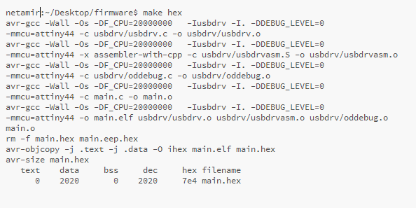
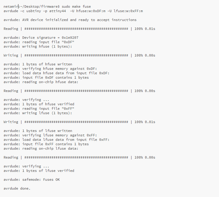
Third Step is: make Fuse - which gave response from the system:
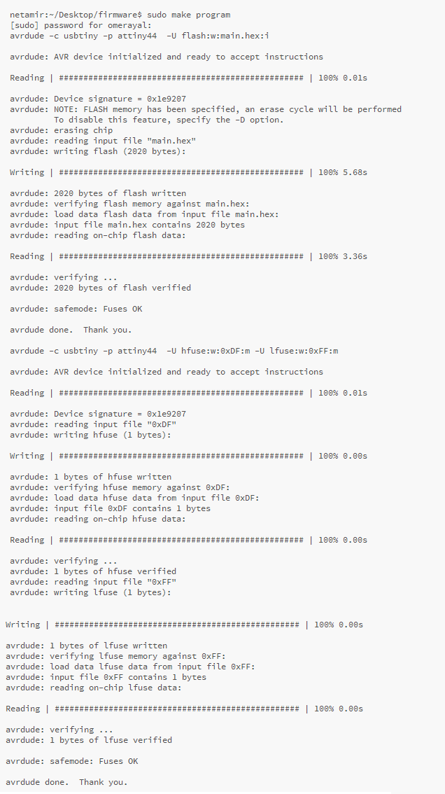
Fourth Step is: make program - which gave response from the system:
WhenPrograming was done I had to remove soldered bridges from the board
Last step was conecting fabisp to my computer and i received the message:
USB connection: FABISP