This week our goal is to read a microcontroller data sheet and to program our board to do as many things in as many ways as possible.
I hooked up my board from 2 weeks ago and tried to use the arduino front end to "burn a bootloader" to set the timing. It did not recognize my board. I never checked the board when I made it, so there was a possiblilty that there was a hardware problem.
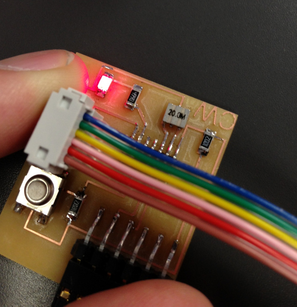
I checked the traces' continuity with a multimeter and when I touched a pin, the board worked. I went over to the soldering station and resoldered the pin that seemed to be the problem. I hooked it back up to the computer and everything worked. I downloaded some sample sketches and after changing the pins to match the microcontroller that we used, everything seemed to work.
I was a bit discontent with this however, and decided that I would recreate the board that I made, but this time I would add an additional LED. I went into EAGLE and added the LED and a resistor, taking the opportunity to revise my design from last time, taking into account the parts that were a bit challenging to solder. I went ahead and milled the new board and when I went to cut it out, it cut my traces on one edge completely off the board! I redesigned the traces, and remilled the board. This time it was a success.
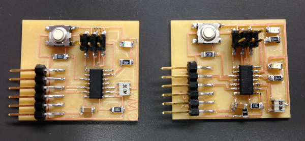
I went ahead and started to stuff the board, but realized that I missed a connection on my design. One of my resistors was only connected on one end. Reluctant to try a third time for a good board, I soldered a 0 resistor to connect the part to the trace. It was a bit kludgy, but it worked. (or so I thought).
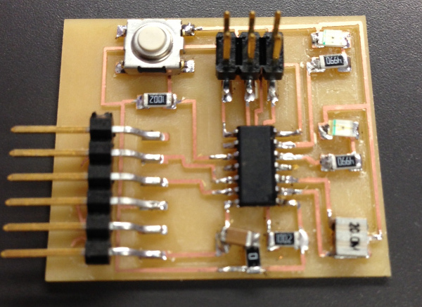
When I went to power up the board, it also didn't work. I went back to the trusty multimeter and found a bad solder connection. After minor repairs, everything worked.
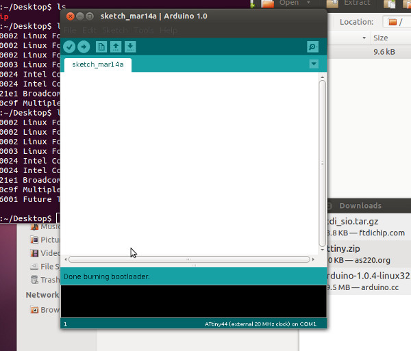
I now could rewrite the Arduino sketch to turn on and off both LEDs. I experimented with various loops, trying to remember my brief training in object-based coding from 20 years ago (Pascal). I spent many hours trying various variables and loops including a sketch that turns the LED #1 off when you press the button, on when you release, but also increments so that after 10 tries, both LEDs turn off. This is a type of routine that I need for my project, if I decide to make the puzzle box that I originally intended.
The data sheet was very long, and mostly very difficult to understand, but I was surprised at the large amount of information. Knowing what each pin is assigned to do is very useful, and much of the other information helped me to gain a better understanding of what specifically the chip can do. Still, I feel that a lot of the information was still a bit above my current understanding, but perhaps it will be better after a few more weeks of experimenting with the electronics.