This week our goal is to make a FabISP in-circuit programmer.
This week we will learn to use the Modela milling machine to remove the excess copper from a FR1 PCB leaving the traces from a design, adding surface-mount components (stuffing), attaching it to an already working in-circuit programmer, programming the board, and finally removing 2 bridges to finalize theFabISP.
The first half of the week was spent installing the Modela milling machine. Unlike many labs who have a MDX-20 machine, we have a MDX-40. The fab modules were not created with that in mind, so we needed to modify the files so that they would work with the newer machine. Blair Evans from the Detroit Incite Focus lab spent many hours troubleshooting the various problems until, at last we managed to get the machine moving with fab module commands. It was necessary to set the x and y origin point using the windows software, but the remainder could be done with the fab modules. Once we managed to get it cutting and tried it out, it stopped partway through the cut. Repeated attempts proved that it stopped partway through every cut. Blair managed to figure out that it was related to a different install of Ubuntu on the machine that controls the milling machine. Once the appropriate fixes were added, the machine worked. Unfortunately, it was now Monday morning, and we had only a couple of days before class on Wednesday to complete the remainder of the week's assignment.
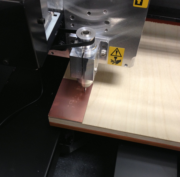
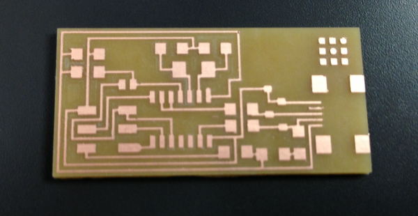
I placed the board on the cutting surface (with a sacrifical board underneath just in case) and zeroed the bit on the surface to the board. The first attempt of cutting the board failed, but only because a part of the board must have been a bit lower than the rest of the board. Without removing the board, I zeroed the z-axis on the poorly cut portion (the lowest) and recut the board. Success!
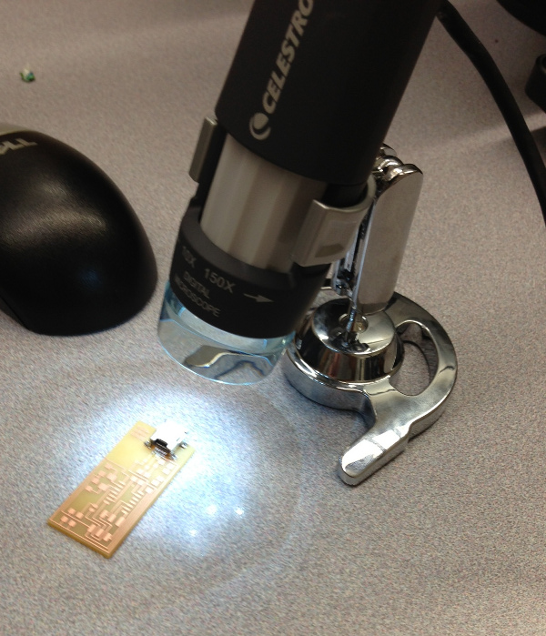
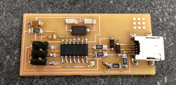
Now came the time to stuff the board. Starting with the mini-USB header, I began to solder the parts onto the board. The connections on the header are very small and I was unsure if they were good connections. I set up the digital microscope and verified that the connections appeared solid.
As I continued to add parts to the board I found myself working more and more quickly with fewer errors. I have soldered many times in the past, but rarely on a PCB. When all was added, the parts were not very well-aligned, but all of the connections appeared sufficiently solid.
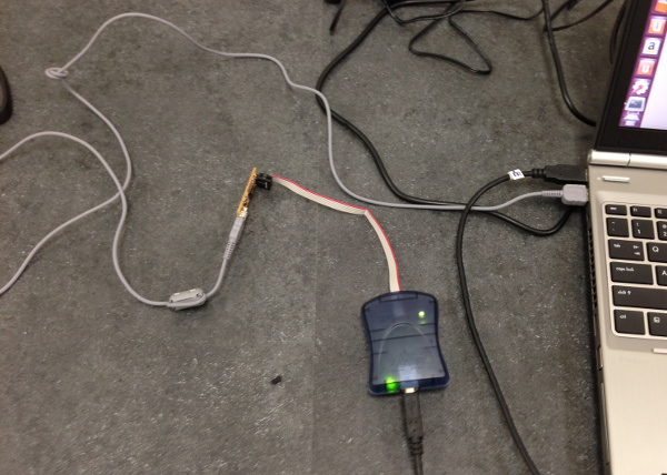
I connected the board to the ISP and was pleased to notice that I had both lights green. Green is good! I began to run the commands to add the program to the board. All went well until I ran the make hex command. I had many errors. Looking at the specific errors, it appeared that they were problems with the code, not the hardware. Since many other students are using the program without difficulty, I assumed that the problems were probably again tied to the version of Ubuntu that we are running. I installed the LTR version on my laptop and repeated the instructions. This time everything worked. I removed the 0 resistor and the solder bridge and declared victory. It even appears as a USB device. Success!