Output Devices
Lesson 13
This week's assignment is to add an output device to a microcontroller board and program it to do something.
This class, i wanted to work with a led array and a stepper motor and/or servo. With my end project in mind, these skills will be the most usefull. I made the array board by milling out the path (traces and interior) with the modula. I had some problems with the modula, as it was not cutting deep enough into the board to actually make a path. It actually just scratched the surface. Bas pointed out to me, that the board had some room to move downward when you press on it. So when the machine presses on the board, i will bend and therefor not cut into the board. I let the modula finish the program and reset the high of the drill by pressing on the board, while setting z. When i ran the program again, the modula cut deep enough to make a path.
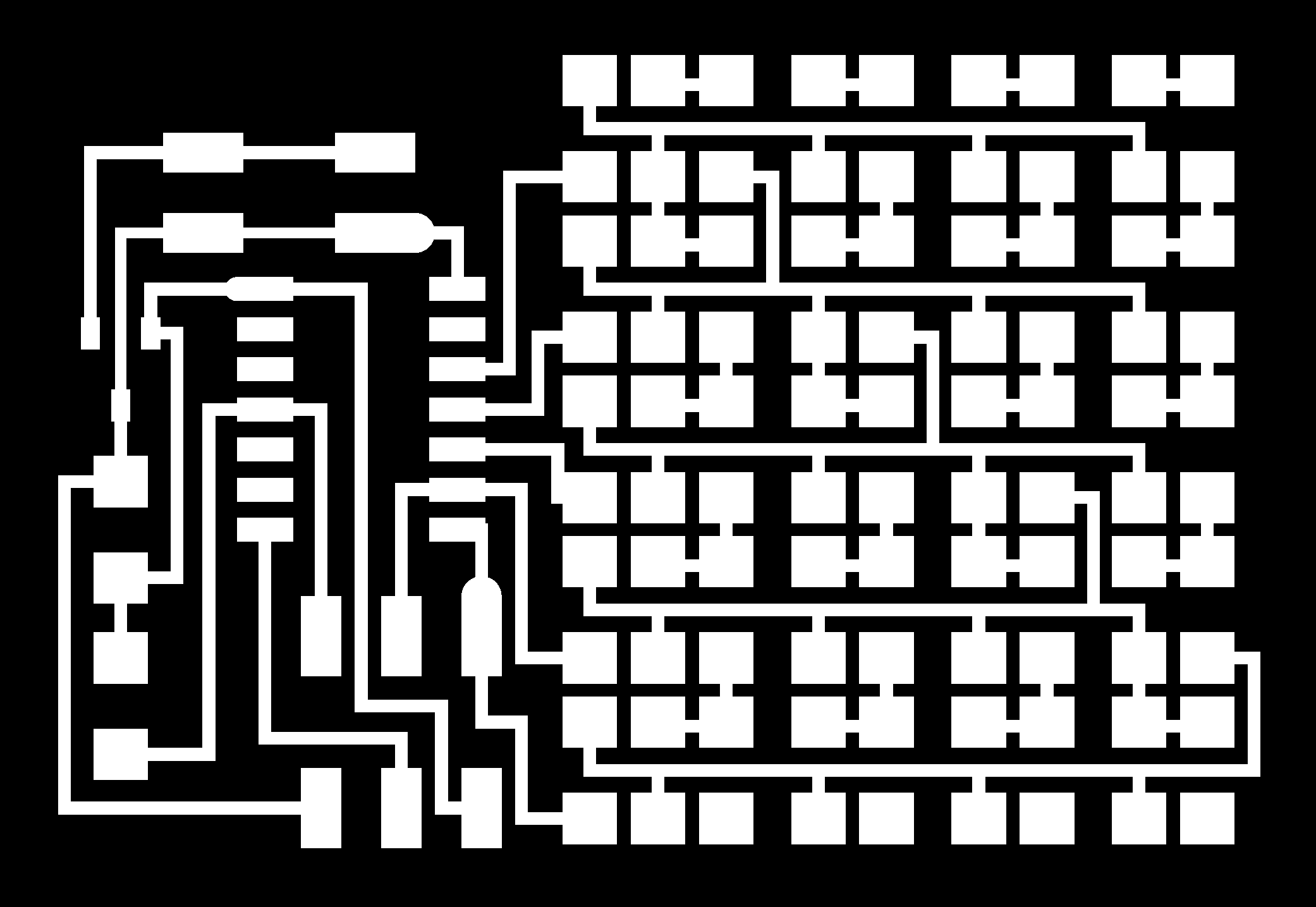
Next step was to solder all the leds on the board. It was a tedious task to get all the components on the board and not making them touch on the wrong places, but i managed it in the end.
I downloaded the makefile and the hello.array.c file and created a directory within the WINAVR directory. I connected the board to my usbtiny and to the 9v battery and typed the following code within the created directory:
make clean
make -f hello.array.44.make
make -f hello.array.44.make program-usbtiny
make -f hello.array.44.make program-usbtiny-fuses
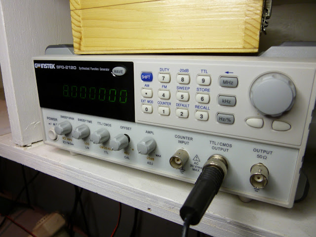
When i finished programming the board, nothing happened. I checked all the connections, but could not find the problem. Bas pointed out to me, that my board does not have an external clock. I programmed the microprocessor with an external clock, with the fuses command, so it did not run. I had two options, either i had to replace the microprocessor with another or i could simulate a clock with a function maker and then reprogram the fuse. I decided to do the latter.
Bas set the function generator (see below) to 8Mhz and i looked up in the datasheet where the clock should be connected to and which commands i should send to the microprocessor to reprogram the fuse. I found the clock port in the datasheet, which is PB0 for an attiny44 board. I typed "reset attiny44 fuse" in google and found this webpage which explains how to reset a fuse.
From the code in the the makefile (below), i concluded that the lfuse is being set to 0x7E, so i looked in the resetting code for lfuse. The webpage with the resetting code says that i should set lfuse for attiny44 to 0x62.
avrdude -p t44 -P usb -c usbtiny -U lfuse:w:0x7E:m
We set the function maker and knew where to connect it to and we had the program to reprogram the fuse. Bas connected the function maker to the PB0 port and i reprogrammed the fuse with the following command:
avrdude -p t44 -P usb -c usbtiny -U lfuse:w:0x62:m
The board worked!
I wanted the Led array board to display numbers, so i changed the Neil's original hello.array.44.c code to hello.array.44.count.c. The result of this code can be seen below:
The second board, i made was the unipolar stepper board. I did not encounter any problems making this board. The most tedious task was to get the cables from the stepper in the right order, so i would connect with the board. I aligned the cables of the stepper in the order indicated on the board. I programmed the board as i did with the led array board with hello.stepper.44.wave.c and hello.stepper.44.make and this was the end result:
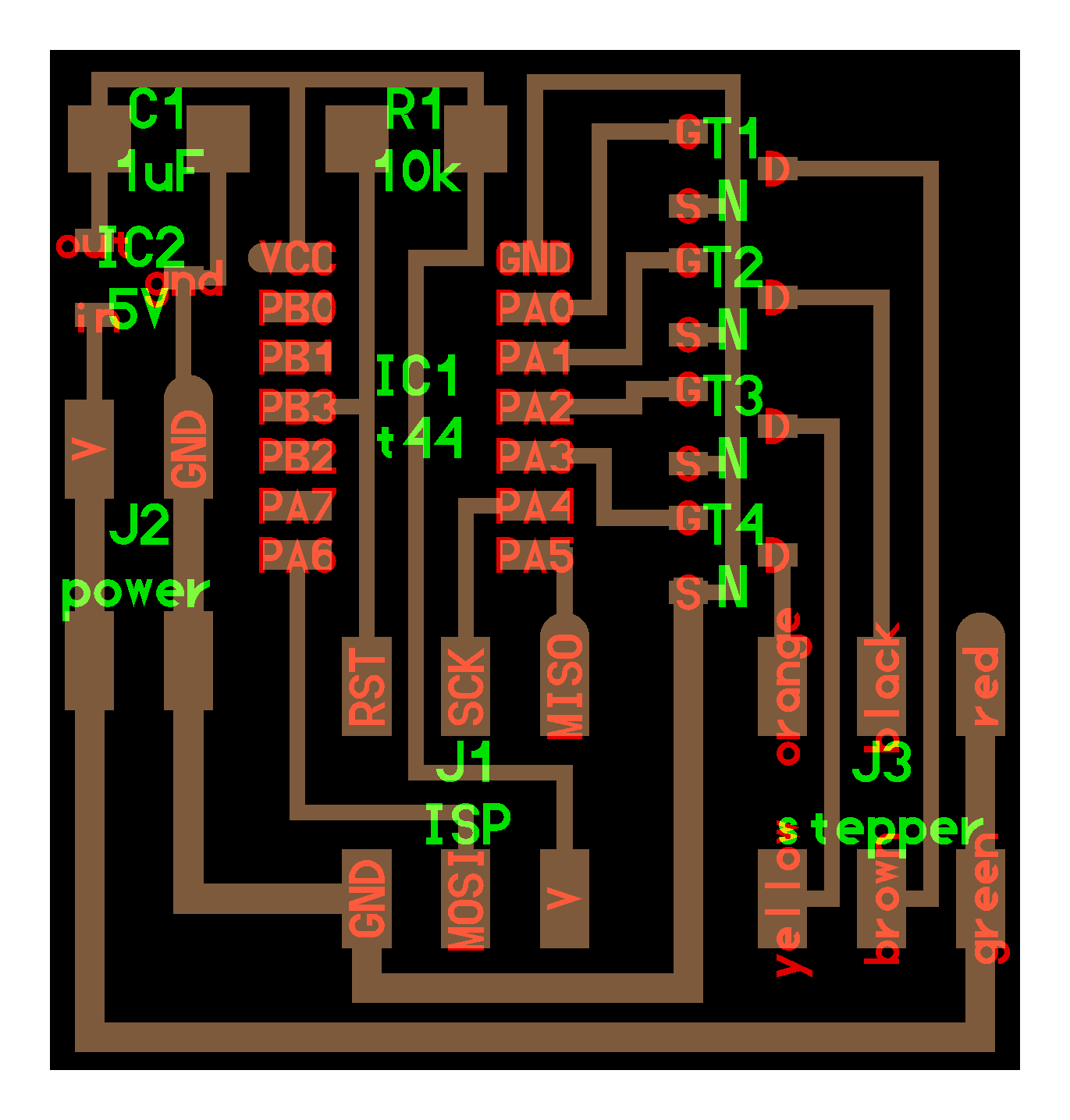