Academy 2013
My troll head
The head
I made a troll head in the Shopbot. At first I
sculpted in a program called Sculptris.


After that I had eight pieces to cut out.
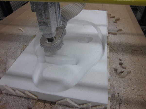
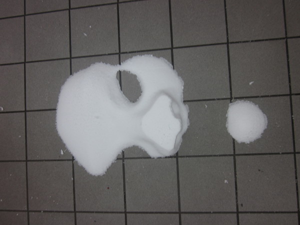
Here is a picture of on layer being cut out
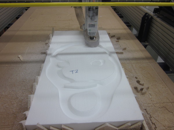
The Styrofoam is week material so I wanted to make the Shopbot go as fast as possible. To make that happen I only made finishing toolpath so the machine began cutting the head straight away without cutting it into dozens of layers like it would if the material had harder, for example wood.
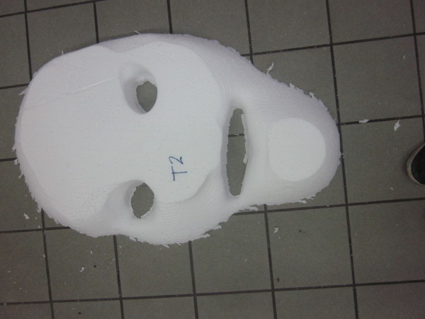
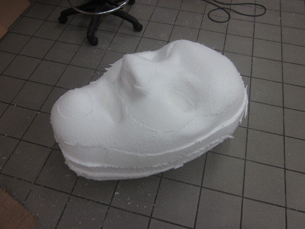
Here are all of the layers together
The Circuit board
The most difficult part about the
final project was programming the
circuit board. The idea was to have a
servo board which controlled two
motors. From the board there would be
two buttons, one for right movement
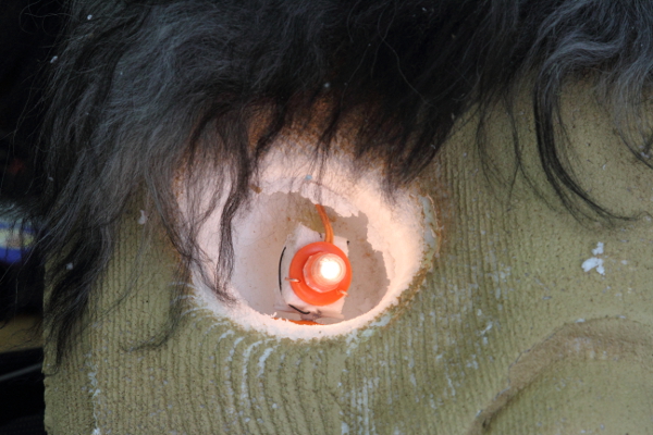
and one for left. The motors would
then spin the eyes of the troll left
or right.
Arduino
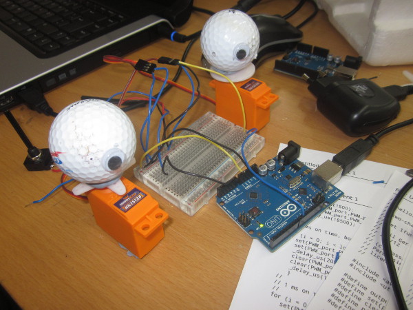
The first thing I did was connecting
the board to an Arduino to get a
better look on what I was trying to
do. As you can see on the picture
below there is an variable resistor
there. I used that to controlled the
movement of the eyes.
This method worked out well but
converting it into an hello board was
a lot more work than I thought.
hello.servo
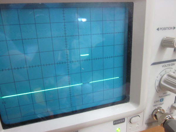
I used Neil's servo board in the
beginning. I brought out the old
oscilloscope to help me find the Pulse
Width Modulation (PWM). The problem
was that the pulse the program was
sending was well over what the servo
could handle. So the servo motor just
vibrated constantly.
I did all the programming a program called Atmel Studio 6.1.
I noticed a line on top of the file
that said set lfuse to 0x7E for 20
MHz xtal. I found where I could
set the lfuse in Atmel Studio but
nothing happened. Then I got an advice
from a friend who told be to write #
define F_CPU 20000000. This line
defined the 20 MHz crystal.
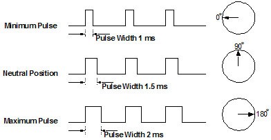
Then I tried different variations on
the pulse to get the right curve on
the eyes movement. On the picture
below I saw that the pulse had to be
between 1 and 2 ms. Otherwise the
motor would go further then it is
suppose to go.
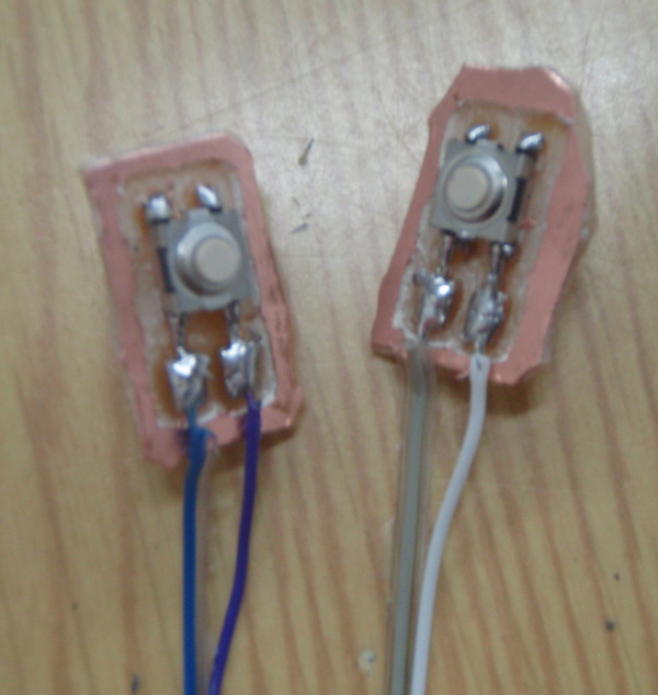
Now I had to connect an output to the eyes so I could control them. On the ATtiny44 are some unused pins (PA0, PA1, PA2, PA3) so the idea was to use them to control the button inputs.
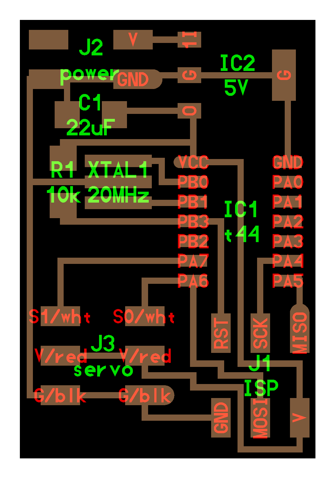
hello.servo board
This is how i defined the Led light
#define LED (1 << PA2)Now all I had to do was make another button, connect both of them to the movement of the motors and define them as left or right buttons.
#define LED_direction DDRA
Here is the full code I used for the programming:
// Based on hello.servo.44.2.c
//
// two-channel software PWM servo motor hello-world
//
// set lfuse to 0x7E for 20 MHz xtal
//
// Neil Gershenfeld
// 4/8/12
//
// modified by Bjartur Tyr
// Fablab Vestmannaeyjar
// 12/6/2013
//
// (c) Massachusetts Institute of Technology 2012
// Permission granted for experimental and personal use;
// license for commercial sale available from MIT.
//
# define F_CPU 20000000

#include <avr/io.h>
#include <util/delay.h>
#define output(directions,pin) (directions |= pin) // set port direction for output
#define set(port,pin) (port |= pin)                // set port pin
#define clear(port,pin) (port &= (~pin))           // clear port pin
#define pin_test(pins,pin) (pins & pin)            // test for port pin
#define bit_test(byte,bit) (byte & (1 << bit))     // test for bit set
#define position_delay() _delay_ms(1000)
#define PWM_port PORTA
#define PWM_direction DDRA
#define PWM_pin_0 (1 << PA6)
#define PWM_pin_1 (1 << PA7)
#define input_pins PINA
#define loop_count 1

#define input_pin1 (1 << PA0)       // defining PA0 as right button
#define input_pin2 (1 << PA2)       // defining PA2 as left button
int main(void) {
    //
    // main
    //
    uint8_t i;
    //
    // set clock divider to /1
    //
    CLKPR = (1 << CLKPCE);
    CLKPR = (0 << CLKPS3) | (0 << CLKPS2) | (0 << CLKPS1) | (0 << CLKPS0);
    //
    // set PWM pins to output
    //
    clear(PWM_port, PWM_pin_0);
    output(PWM_direction, PWM_pin_0);
    clear(PWM_port, PWM_pin_1);
    output(PWM_direction, PWM_pin_1);
    //
    // main loop
    //
    while(1){
        //
        // here the motor stays still
        //
        // if button 1 is pressed?
        //
        if (pin_test(input_pins,input_pin1) == 0) {
            for (i = 0; i < loop_count; ++i) {
                set(PWM_port,PWM_pin_0);
                set(PWM_port,PWM_pin_1);
                _delay_us(1800);                // this number turns the eye left
                clear(PWM_port,PWM_pin_0);
                clear(PWM_port,PWM_pin_1);
                _delay_us(19000);
            }
        }
        //
        // if button 2 is pressed?
        //
        else if (pin_test(input_pins,input_pin2)==0) {
            for (i = 0; i < loop_count; ++i) {
                set(PWM_port,PWM_pin_0);
                set(PWM_port,PWM_pin_1);
                _delay_us(800);                   // this number turns the eye right
                clear(PWM_port,PWM_pin_0);
                clear(PWM_port,PWM_pin_1);
                _delay_us(19000);
            }
        }
        //
        // no button pressed
        //
        else {
            for (i = 0; i < loop_count; ++i) {
                set(PWM_port,PWM_pin_0);
                set(PWM_port,PWM_pin_1);
                _delay_us(1300);              // this number makes the eye watch forward
                clear(PWM_port,PWM_pin_0);
                clear(PWM_port,PWM_pin_1);
                _delay_us(19000);
            }
        }
    }
}
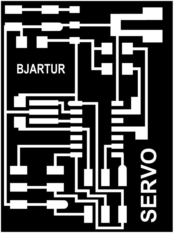
Circuit Board
After I got the motors
spinning with Neils board I
had to make my own. I put two
resistors on the breadboard
when I was working with the
original servo board so I had
to make room for them. The
resistors were 1 kΩ and 10 kΩ.
I also had to make patches
next to the ATtiny so I had
more space to solder the
wires for the buttons on.
Here is a picture
of the servo board edited by
me
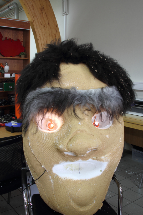
In the end here are two pictures of the head after it is finished
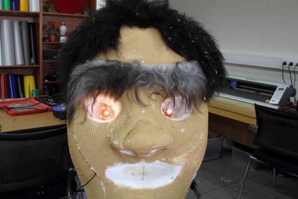
Final Project Presentation
