Academy 2013
My screen in a box
hello.lcd
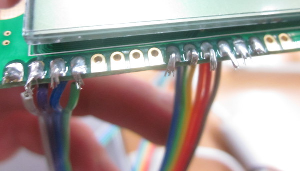
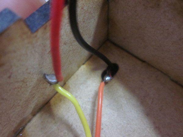
My favorite project this week was to make a LCD screen. I began soldering the board and than I had to solder the screen to it. I looked at Neils video to see how the wires where connected to the board and followed that.Here are the wires soldered to the
screen
Now I had to program the board and wrote in the terminal
         ~/Desktop/hello.lcd$ sudo make -f hello.LCD.44.make
         ~/Desktop/hello.lcd$ sudo make -f hello.LCD.44.make program-avrisp2
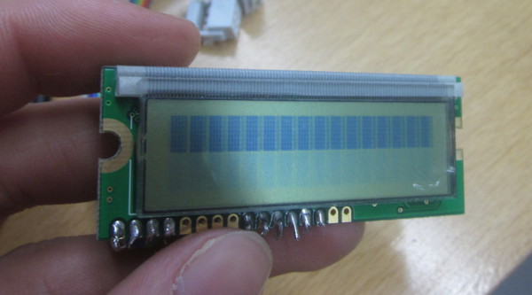
Here is the screen not working
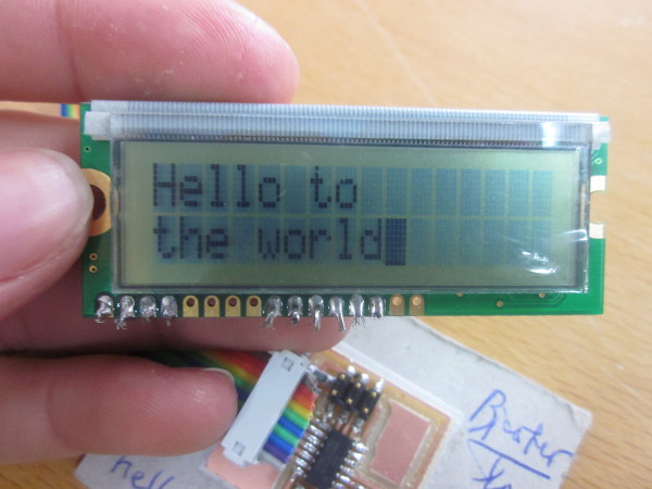
After that I got an error and had no idea why it came up. After few seconds I noticed that I had forgotten to plug the battery on the board so it wasn't getting any power. After I did that everything went fine on the board and on the screen appeared the text "Hello to the world". That meant that the program was running fine. Now I ran the .c file and wrote:
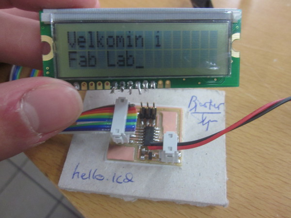
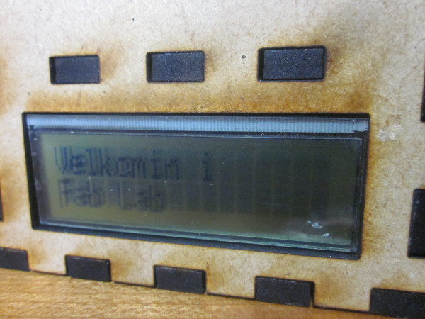
gedit hello.LCD.cIn there I changed the text from "Hello to the world" to "Velkomin í Fab Lab" witch means "Welcome to Fab Lab". This project was suppose to be a good example of what people can make in Fab Lab when the come in for the first time.
Hello to the world!
Velkomin í Fab Lab
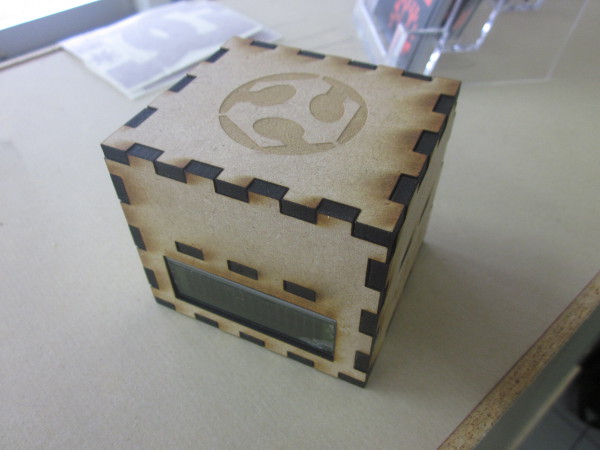
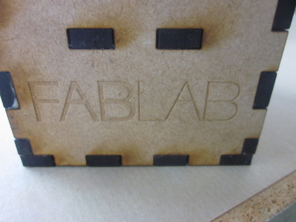
I then raster in the laser cutter the Fab Lab log on it and made holes for the battery wire.
The screen comfortably placed in the box
Here are the walls of the box

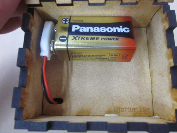
Here is the battery in the top shelf
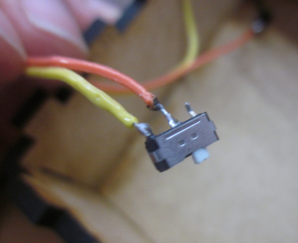
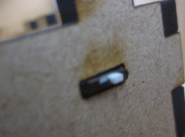
Here is the slide switch connected to
the
battery snap
Here is the switch in place
hello.RGB
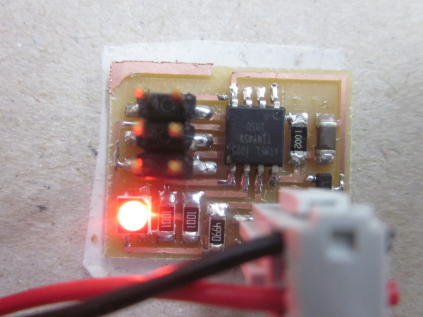
I made this hello.RGB board after I did the screen. RGB stands for Red, Green and Blue which are the colors that the board makes. I programmed the board the same way I programmed the screen and I got the light shining. I'll have to give myself more time to change the codes for it.hello.RGB
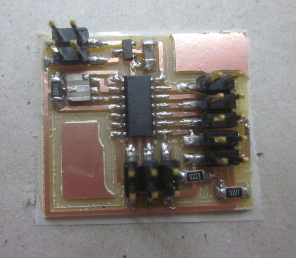
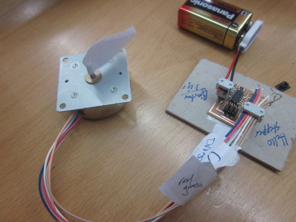
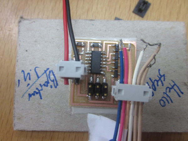
hello.stepper
I made the unipolar hello.stepper motor few weeks ago.
After I soldered the board and programmed it the motor
just vibrated in circles instead of turning more
consistently. I asked Neil last week and he told me that
the motor was not connected right. I haven't found time to
dig in to that but that will defiantly be my next project
here in Fab Lab.
I also soldered some other output devices but I had to
stop making them because we didn't have all the objects
for the boards.
Here are some pictures of the stepper
motor