Fab Academy 2013 · Michael Hviid Nielsen
Waag Society's Fablab in Amsterdam
· Lecture 18: Invention, Intellectual property, and Income
Lecture 18: May 15, 2013
Assignment:
Develop the final project and
Develop a plan for dissemination of your final project
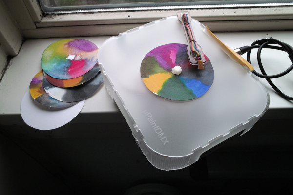
Prototyping the "µPaintDMX Controller"
SHIELD
Using Arduino Duemillanuove
and This shield:
(already owned it) bought prefabricated here:
http://www.cutedigi.com/dmx512/dmx-512-io-shield-bare-pcb-board-for-arduino.html
The shield is consisting of almost nothing - basically a DMX tranceiver (which is a level-shifter from the 3.3V output of the digital signals from the arduino to the 5V levels needed for RS-485 compliance which the DMX-512 protocol is a part of) and couple of 5-pin XLR connectors for I/O. The shield really ought to implement some form of isolation (galvanic or optical) to prevent damage to equipment if hooked up wrongly (only DMX 512-A not the 1992 DMX-512?). This will be accessed when developing the final project.
First test with mock-up/prototype is done with the DMXSimple Arduino library from TinkerIT
(Filename: DmxSimple_v3.zip)
And the video tutorial linked to from the same place:
http://vimeo.com/3453833
After the protoype works, I will move the development to a Boarduino (which is one of the "Fab lab Arduinos"):
http://www.fabacademy.org/content/projects/barduino/
It is arduino-compatible in the sence that its the same chip - but the available I/O-pins are reduced.
This shield:
https://www.tindie.com/products/Conceptinetics/25kv-isolated-dmx-shield-for-arduino-5-pin-xlr/
Has some clever jumpers added - as well as protection. Esp. the disable jumper is nice!
LAMP
The prototyping also includes this DMX-controllable LED light fixture from American DJ:
http://www.americandj.com/ProductDetails.aspx?ItemNumber=2027
From the user-manual of the lamp here:
http://www.americandj.com/pdffiles/micro_wash_rgbw.pdf
The DMX-adress of the lamp is set on the back of the lamp via dip-switches
As so much available "DMX" equipment, the lamp is equipped with 3 pin XLRs which is not part of the DMX standard. So a converter cable was made with a 5-pin plug in one end and a 3-pin XLR plug in the other. The cable uses DMX-512 standard compliant cable with an impedance of 110 Ohms (the standard allows for 100 to 120 Ohms impedance). The lamp can be terminated internally (via a 120 Ohm resistor across the data-lines to "eat up" the signal so it can't echo/ring back the cable and mix with the new data being sent) so a discreet terminator wasn't needed for prototyping.
SENSOR
The prototyping also includes this color sensor:
http://www.ams.com/eng/Products/Light-Sensors/Color-Sensor/TCS3414
Bought already on a breakout board on Ebay from this seller:
http://www.ebay.com/itm/Light-Color-Sensor-I2C-16-bit-RGBW-Controllers-Arduino-w-Pins-Tiny-/330921825832?pt=LH_DefaultDomain_0&hash=item4d0c7a5628
From the datasheet here:
http://www.ams.com/eng/content/download/250258/975997/142735
It is obvious that using this sensor when bought alone ($3 from Mouser or Digikey) is a challenge due to its dimensions (at 2095x1875 micron) is that it is tiny and that the package is 3x3 BGA (Ball Grid Array) with only 0.61 mm between centers of the balls in one of the directions. It could probably be done on the Roland Modela if the center pin where brought out to the underside by a via but since the time available for the Final Projects are limited, I chose to buy a sensor already on a breakout board. The aim is that at some point in the future - the sensor itself will be Fab-labbable and not just bought.
The sensor is basically an CMOS sensor as found in a digital camera - but only with 16 photosites. Four of them with a Red filter, four with a Green filter, four with a Blue filter - and the last four with no filter in front (therefore "white"). So the sensor can register the amounts of RGB and W (illumination). Each channel can be individually calibrated for gain - and the sensors 16-bit RGBW output read via I2C at up to 400 kHz.
From:
http://www.maxwellrosspierson.com/2012/11/18/interfacing-the-arduino-to-the-taos-tcs3414-via-i2c-continued/
We get this comment:
"Some helpful hints on hardware: It turns out that as long as you have only one 3.3V device on the i2c bus, you don’t have to have the level shifter circuit I was using, you can connect it directly to the i2c pins (but power it via 3.3V supply, not 5V). So that’s simpler. Also, Taos recommends a .1μF decoupling capacitor between the 3.3V supply and ground, located adjacent to the unit, to reduce fluctuations due to logic level shifting:"
And alink to code made by Tiuri De Jon:
http://www.maxwellrosspierson.com/2012/11/18/interfacing-the-arduino-to-the-taos-tcs3414-via-i2c-continued/2012-11-18-light_meter_rev5/
It looks like this:
          // TCS3414 receiver code rev 5

          // Developed by Tiuri de Jong, with contributions by Max
          Pierson

          // This software is released under WTFPL, although credit and
          share-alike are appreciated.

          // 18 November 2012


          //include the library for i2c

          #include


          unsigned int TCS3414values[4]; // [Clear,Red,Green,Blue]

          float TCS3414medium[4]; // [Clear,Red,Green,Blue]

          float TCS3414mediate[4]; // [Clear,Red,Green,Blue]

          float ColorTemperature = 0;


          // SET the integration time here. Higher times allow for
          higher values with better precicion.

          int integrationtime = 400; //12 == 12ms, 100 = 100ms, 400 =
          400ms. Other values are note accepted

          int loopdelay = integrationtime; //loop delay depends on the
          integration time


          boolean debug = false; //change to true if you want to see the
          various debug serial output bits

          boolean percentageEnabled = false; //enable/disable the
          percentage mode

          boolean compensateEnabled = false; //enable/disable color
          compensation of the sensor sensitivity per color


          void setup(){

          Wire.begin();// join i2c bus (address optional for master)

          Serial.begin(9600);//115200

          while (!Serial) {

          ; // wait for serial port to connect. This while loop is
          needed for the Arduino Leonardo only

          }

          CMD(0);

          TCS3414Start(14,2000);

          }


          //The main function.. This repeats itself forever!

          void loop() {

          getSerialCommands(); //to be able to receive commands


          //gets the raw values from the sensors and writes it to
          TCS3414values[]

          TSC3414All(TCS3414values);


          //compensate based on the filter characteristics of the
          TCS3414

          if(compensateEnabled)

          colorCompensator(TCS3414values);


          //keeps a running average from the last 4 values per color.

          calculateMedium(TCS3414mediate,TCS3414values,4.0);


          //calculates the color temperature, using the algorithm in the
          TCS3414 datasheet

          ColorTemperature = CCTCalc(TCS3414values);


          //displays percentage values, if enabled.

          if(percentageEnabled){

          makePercentage(TCS3414values, TCS3414medium);

          }


          Serial.print(“Clear: “);

          Serial.print(TCS3414values[0]);

          if(percentageEnabled)

          Serial.print(“%”);

          Serial.print(“\tRed: “);

          Serial.print(TCS3414values[1]);

          if(percentageEnabled)

          Serial.print(“%”);

          Serial.print(” \tGreen: “);

          Serial.print(TCS3414values[2]);

          if(percentageEnabled)

          Serial.print(“%”);

          Serial.print(“\tBlue: “);

          if(percentageEnabled){

          Serial.print(TCS3414values[3]);

          Serial.println(“%”);

          }else{

          Serial.println(TCS3414values[3]);

          }


          delay(loopdelay); //delays by the integration time between
          measurements


          }//end loop()


          /*

          * ======================================================

          * Calculation functions

          * ======================================================

          */


          /*** takes the raw values from the sensors and converts them
          to

          Correlated Color Temperature. Returns a float with CCT ***/

          float CCTCalc(unsigned int allcolors[]){

          float TCS3414tristimulus[3]; // [tri X, tri Y, tri Z]

          float TCS3414chromaticityCoordinates[2]; //chromaticity
          coordinates // [x, y]


          //calculate tristimulus values (chromaticity coordinates)

          //The tristimulus Y value represents the illuminance of our
          source

          TCS3414tristimulus[0] = (-0.14282 * allcolors[1]) + (1.54924 *
          allcolors[2]) + (-0.95641 * allcolors[3]); //X

          TCS3414tristimulus[1] = (-0.32466 * allcolors[1]) + (1.57837 *
          allcolors[2]) + (-0.73191 * allcolors[3]); //Y // =
          Illuminance

          TCS3414tristimulus[2] = (-0.68202 * allcolors[1]) + (0.77073 *
          allcolors[2]) + (0.56332 * allcolors[3]); //Z


          float XYZ = TCS3414tristimulus[0] + TCS3414tristimulus[1] +
          TCS3414tristimulus[2];


          //calculate the chromaticiy coordinates

          TCS3414chromaticityCoordinates[0] = TCS3414tristimulus[0] /
          XYZ; //x

          TCS3414chromaticityCoordinates[1] = TCS3414tristimulus[1] /
          XYZ; //y


          float n = (TCS3414chromaticityCoordinates[0] – 0.3320) /
          (0.1858 – TCS3414chromaticityCoordinates[1]);


          float CCT = ( (449*pow(n,3)) + (3525*pow(n,2)) + (6823.3 * n)
          + 5520.33 );


          Serial.print(“Illuminance: “);

          Serial.print(TCS3414tristimulus[1]);

          Serial.print(“\tx: “);

          Serial.print(TCS3414chromaticityCoordinates[0]);

          Serial.print(” \ty: “);

          Serial.print(TCS3414chromaticityCoordinates[1]);

          Serial.print(” \tCCT: “);

          Serial.print(CCT);

          Serial.print(“K\t — \t”);


          return CCT;

          }


          /*** Keeps a running average of 4 values per color. ***/

          void calculateMedium(float med[], unsigned int value[], float
          divider){

          for(int i = 0; i < 4; i++){

          med[i] = ( (med[i]*(divider-1.0)) + value[i] ) / divider;

          }

          }


          /*** calculates percentages for R,G,B channels, if enabled.
          ***/

          void makePercentage(unsigned int allcolors[], float
          allmedium[]){ //makes every color a percentage, 100% is the
          average of the previous 4 values before this is entered.

          for(int i=0; i 0){

          int receive_command = Serial.read();

          if(receive_command == 49){//49 == 1

          Serial.println(“Percentage enabled, max value (100%) set to
          current medium”);

          percentageEnabled = true;//enables/disables percentage mode.

          for(int o = 0; o < 4; o++){

          TCS3414medium[o] = TCS3414mediate[o];

          }

          }else if(receive_command == 48){//48 == 0

          Serial.println(“Percentage disabled”);

          percentageEnabled = false;//enables/disables percentage mode.

          }else if(receive_command == 63){//63 == ?

          CMD(2000);

          }else if(receive_command == 112){//112 == p

          Serial.println(“pausing for 5 seconds (stackable)…”);

          delay(5000);

          getSerialCommands();

          }else if(receive_command == 99){//99 == c

          Serial.println(“Color compensation enabled”);

          compensateEnabled = true;

          }else if(receive_command == 110){//110 == n

          Serial.println(“Color compensation disabled”);

          compensateEnabled = false;

          }else{

          Serial.print(“The command entered ( “);

          Serial.print(receive_command);

          Serial.println(” ) was NOT found in the command list”);

          }

          }

          }


          void CMD(int delayTime){

          Serial.println(“=========== Command list ===========”);

          Serial.println(“\’ \’”);

          Serial.println(” ? == Show this command list”);

          Serial.println(“”);

          Serial.println(” p == pause for 5 seconds (stackable)”);

          Serial.println(“”);

          Serial.println(” 1 == Enable Percentage mode”);

          Serial.println(” 0 == Disable Percentage mode”);

          Serial.print(” Percentage mode is currently: “);

          if(percentageEnabled){

          Serial.println(“ON”);

          }else{

          Serial.println(“OFF”);

          }

          Serial.println(“”);

          Serial.println(” c == Enable Color compensation mode”);

          Serial.println(” n == Disable Color compensation mode”);

          Serial.print(” Color compensation mode is currently: “);

          if(compensateEnabled){

          Serial.println(“ON”);

          }else{

          Serial.println(“OFF”);

          }

          Serial.println(“\’ \’”);

          Serial.println(“====================================”);

          delay(delayTime);

          }
Note on Pull-Up resistors for I2C:
"somewhere", namely in a node here:
http://code.google.com/p/arduino/issues/detail?id=506
I found this remark:
<SNIP>
I2C is open drain, meaning that master and slaves never actively drives the signal high. The line is pulled up high and the devices communicate only bringing it low. So, when you have to communicate with a 3V3 device, if you pullup to 3V3 and you disable the 5V pullups, as the ATMEGA will take any signal >= 2.6 as high, you'll be perfectly fine even without a logic level converter.
<SNAP>
and this:
<SNIP>
Hi there,
currently Wire (through twi_init()) enables by default the internal pullups of the uC.
As all 16MHz runs at 5V this means that with pullups enabled signals will have a 5 volt on logic level. Unfortunately, as many I2C devices runs at 3 Volts and aren't 5Volts tolerant, sending 5V signals to them is clearly a very bad idea.
I would propose making the pullpus enabling optional and off by default. In my experience, people overlook the fact that Wire does enable the pullups causing possible problems on the I2C devices used.
Moreover, tests (http://www.dsscircuits.com/articles/effects-of-varying-i2c-pull-up-resistors.html) have shown that internal pullups performs extremely bad in terms of signal quality and bus speed. So, they shouldn't been used anyway.
In case this is accepted, I'll gladly submit a patch for this.
Thanks,
Fabio Varesano
<SNAP>
For the Wire.h library - internal pull-up resistors are on by default pulling the signal to 5V! not 3V
Code to disable internal pull-up:
Then:
Add external pull-up resistors (4k7 ohms - why?)
Or:
Just use the 3v3 on the arduino instead of the 5V vcc??
To disable them in code:
http://www.varesano.net/blog/fabio/how-disable-internal-arduino-atmega-pullups-sda-and-scl-i2c-bus
Do this:
Just use the following code to disable the internal pullups in any code after you initialized Wire (using Wire.begin()). This is a good solution to implement in your Arduino library code.
 #ifndef cbi

          #define cbi(sfr, bit) (_SFR_BYTE(sfr) &= ~_BV(bit))

          #endif


            #if defined(__AVR_ATmega168__) ||
          defined(__AVR_ATmega8__) || defined(__AVR_ATmega328P__)

              // deactivate internal pull-ups for twi

              // as per note from atmega8 manual pg167

              cbi(PORTC, 4);

              cbi(PORTC, 5);

            #else

              // deactivate internal pull-ups for twi

              // as per note from atmega128 manual pg204

              cbi(PORTD, 0);

              cbi(PORTD, 1);

            #endif
Note this:<SNIP>
If you are only using one I2C device, the pull-up resistors are (normally) not required, as the ATmega328 microcontroller in our Arduino has them built-in. However if you are running a string of devices, use two 10 kilo ohm resistors. Like anything, some testing on a breadboard or prototype circuit will determine their necessity. Sometimes you may see in a particular device’s data sheet the use of different value pull-up resistors – for example 4.7k ohm. If so, heed that advice. The maximum length of an I2C bus is around one metre, and is a function of the capacitance of the bus. This distance can be extended with the use of a special IC, which we will examine during the next I2C chapter.
<SNAP>
From the I2C standard documentation, eg. here:
http://www.nxp.com/documents/user_manual/UM10204.pdf
The "high" and "low" level of SDA/SCL is no longer described by a fixed value (eg. 3V) but rather 30% or 70% of Vdd.
But the color sensor used specifies 3V input - so external pull-up resistors will be needed in this case.
There is a specific note about external pull-up resistors or using level-shifters here:
http://playground.arduino.cc/Main/I2CBi-directionalLevelShifter
4k7 ohm resistors to 3.3V is recommended (if level-shifter are used; 10k resistors);
<SNIP>
Internal pull-up resistors activated by Wire libary.
The AVR microcontroller in the Arduino uses a TWI interface, which is I2C compatible. The SDA and SCL lines can be programmed with internal pull-up resistors. The Wire library of Arduino 1.0 (in 2012) enables those internal pull-up resistors with the function Wire.begin(). Those internal pull-up resistors are connected to +5V which could violate the specifications of the I2C component.
If two pull-up resistors of 4k7 to 3.3V are used, the voltage is only raised a little by the internal pull-up resistors. This is a controversial subject with many opinions, but no one has ever noticed that a chip has been damaged this way (but you do need those two 4k7 resistors).
<SNAP>
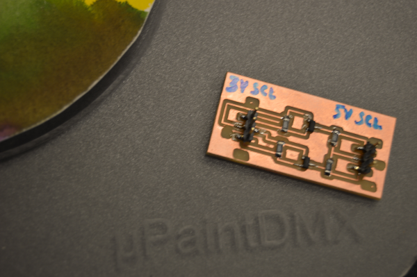
So I chose to use a level-shifter implemented in hardware in order to protect the sensor from the less controlled voltage-levels of the Arduino.
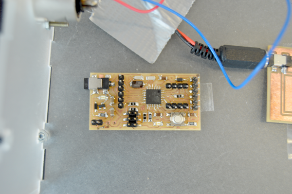
I chose to use the Barduino (a Fab-labable Arduino clone).
Both were pulled in to Eagle. The level-shifter was contructed from an old Philips application note I found on the net after Bas had told me about level-shifters. The Barduino had to be retraced as I needed the specific I2C pins from the Atmel chip brought out to headers in order to read data from the sensor.
Using Mos-FETs for levelshifting is described in detail here:
http://delphys.net/d.holmes/hardware/levelshift.html
The Philips Application Note is here:
http://ics.nxp.com/support/documents/interface/pdf/an97055.pdf
The TTL levelshifter ended up looking like this:
http://www.maximintegrated.com/design/packaging/cad/
Along with a free converter between files (also converts to Eagle)
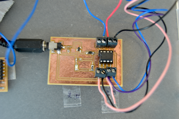
The shield is super simple - nothing more than bringing together the right pins from the barduino to the MAX485 DMX transceiver chip.
The DMX transceiverboard ended up looking like this:
The Barduino ended up looking like this:
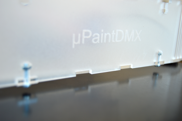
CHASSIS
The original intension was to make the chassis from lasercut birch ply - with cutouts allowing for bending (flexible wood) around the circumference. And with top and bottom snapped in place with tabs. The intension being that the bottom holds the electronics and can be exchanged when the electronics are updated and the top with several solutions for the painting surface - plain wood with a centerpin for precut and archieval/prepainted "Compact Disc"-format sheets of paper, live-paintable silk paper etc. And a milled perspex top with ink wells for live painting.
I changed this to perspex/acrylic - using an array of cutouts along the bend corners. I cut a series of tests using different distances and number of cuts to find a nice compromize between "bendability" and structural strength.
The chassis ended up looking like this:
The pickup is cut in two layers of 3 mm acrylic. The holder for the pickup and the holder for the central "spindle" holding the color designs on top of the surface was printed in PLA on the Ultimaker.
SOFTWARE & LIBRARIES
This library in c/c++ for Arduino:http://sourceforge.net/projects/dmxlibraryforar/files/
Which I found here:
http://playground.arduino.cc/DMX/DMXShield
Is "Gnu Lesser" (LGPLv3) which means it is a free software license which allows for addition of less free modifications before final release - and only the original files are bound by the LGPL license.
The TinkerIt library for Arduino (also GNU Lesser GLP):
http://code.google.com/p/tinkerit/wiki/DmxSimple
Available here:
http://tinkerit.googlecode.com/files/DmxSimple_v3.zip
FILES
Please see class 19: Final Project PresentationPOST FAB ACADEMY DEVELOPMENT
I intent to add a clever form for light fixture adressing - maybe a serial display and a rotary encoder. As well as more than one senser operating simultaneously so that more goups of light fixtures can be controlled.
I will also try to see how far I can take the Fab-Inventory-fication. The XLR-plugs have to be purchased no matter what - but maybe the DMX tranceiver can be virtualized with an AVR plus level-shifters (to convert from 3.3v to 5v signal levels). Maybe the colorsensor itself can be made Fablabbable by using seperate RGB LEDs and a photoresistor. But the LEDs themselves might need to be with a more specific wavelength emmision profile than just the standard LEDs from the inventory (for instance SpectraFill LEDs). Also a means of finding easily obtainable materials for IR- and UV-cutoff filters.
NB! Virtualisation on a AVR is probably not viable. Due to the voltages for sending and receiving DMX exceeding the voltages for the AVRs - the levels needs to be conditioned before reaching - or when leavinf the AVR so that additional are needed for this. Also many DMX tranceivers offers ESD protection build-in (+/-15 KV in the chip I have used). This would also need to be adressed.
I will add an overall brightness output controll (maybe a linear resistor?)
I will add a blackout-button (which overrides current sensor output and sends "0 brightness" to all fixtures until pressed again)
I will add a RGB LED on the console to show what color is send out
PROBLEMS & FIXES ENCOUNTERED DURING MOCK-UP
1. Using DmxSimple library with Arduino 1.0.4 IDE on Win8: the wiring.h file referenced in the DmxSimple.cpp file are now included in the Arduino.h file. FIX: The filename is changed
2. Verifying a sketch exits with errorcode: avrdude: "stk500_getsync(): not in sync: resp=0x00". FIX:
From http://www.parkansky.com/arduino-error.htm:
<SNIP>
There are a TON of pages out there on how to solve this error. The problem is none of them worked for me. The typical solutions range from not having the correct serial port or correct Arduino model board selected under the Tools menu in the Arduino software, to not having a driver (or the correct driver) loaded.
However, the frustating part for me is I KNEW I had the correct serial port and board and driver selected because I was getting output from a sketch scrolling in the Serial Monitor window via a USB connection.
The fix? DISCONNECT ANY WIRES going to pin 0 (RX) while you do the upload. The sketch upload function uses the RX pin.
NOTE: You also need to disconnect any wires going to pin 0 (RX) if you have a sketch with a Serial.read() or Serial.peek() statement, and you want to use the Serial Monitor input field (as shown using the '752' in the example below) to feed data into the running sketch. If you don't disconnect pin 0 it will appear as if your data was entered into your sketch but nothing will happen because the data never truly gets input.
THIS MEANS that my dmx shield has to be removed each time a new sketch is uploaded to the arduino - since pin 0 is tied to the Max485 pin 1 thus preventing upload to the Arduino.
3. Still no output from a simple test-sketch using the video-link for DmxSimple (supplied above). Tried to see if the position of the termination switch on the shield matters (the switch either puts a 120 ohm resistance across pin 2 and 3 - or leaves them open). It doesn't.
4. In DmxSimple.cpp the outpit pin in the following lines was set to pin 3 - on my shield its tied to pin 0. FIX: changed from pin 3 to pin 0, as in:
 static volatile uint8_t *dmxPort;

          static uint8_t dmxBit = 0;

          static uint8_t dmxPin = 3; // Defaults to output on pin 3 to
          support Tinker.it! DMX shield

          <TO THIS>

          static volatile uint8_t *dmxPort;

          static uint8_t dmxBit = 0;

          static uint8_t dmxPin = 0; // Defaults to output on pin 0 to
          support CuteDigi's MaxwellRossPierson's DMX shield
5. Combining code from the creator of the DMX shield (Maxwell Ross Pierson) and the creator of the Arduino Library (Tinker.it) we get this tst-code witch works:
/*

          Based on sample code from Tinker.it - the creator of DmxSimple
          Arduino Library

          Modified and adapted by Michael Hviid Nielsen, 2013

          for a Fab Academy project

          */


          /******************************* Pin
          Outs*****************************/

          // Digital Pin0 on Arduino = Pin1 of MAX485 alias Receiver
          Output

          // Digital Pin1 on Arduino = Pin4 of MAX485 alias Driver Input

          // Digital Pin2 on Arduino = Pin2 of MAX485 alias Receive
          Enable

          // Digital Pin3 on Arduino = Pin3 of MAX485 alias Drive Enable

          /* NB! The state on pin 0 can prevent a new sketch to upload
          on the Arduino*/

          /* So disconnect shield while updating firmware*/


          #include <DmxSimple.h>


          #define RED_CHANNEL 1

          #define GRN_CHANNEL 2

          #define BLU_CHANNEL 3

          #define WHI_CHANNEL 4


          int DMX_RE = 2;

          int DMX_DE = 3;


          void setup() {


            pinMode(DMX_RE, OUTPUT);

            pinMode(DMX_DE, OUTPUT);


            digitalWrite(DMX_RE, LOW);  // Set direction pin
          of transceiver to Rx.

            digitalWrite(DMX_DE, HIGH);  // Set direction pin
          of transceiver to Tx.


            /* The pin used for DMX output. Depends on the shield
          used. If you need to change that, do it here. */

            DmxSimple.usePin(1);


            /* DMX devices typically need to receive a complete set
          of channels

            ** even if you only need to adjust the first channel.
          You can

            ** easily change the number of channels sent here. If
          you don't

            ** do this, DmxSimple will set the maximum channel
          number to the

            ** highest channel you DmxSimple.write() to. */

          //  DmxSimple.maxChannel(4);

          }


          void loop() {

            int brightness;


            /* Simple loop to ramp up brightness  RED */

            for (brightness = 0; brightness <= 255;
          brightness++) {


              /* Update DMX channel to new brightness */

              DmxSimple.write(RED_CHANNEL, brightness);


              /* Small delay to slow down the ramping */

              delay(5);

            }


            for (brightness = 255; brightness >= 0;
          brightness--) {


              /* Update DMX channel to new brightness */

              DmxSimple.write(RED_CHANNEL, brightness);


              /* Small delay to slow down the ramping */

              delay(5);

            }


            /* Simple loop to ramp up brightness GREEN */

            for (brightness = 0; brightness <= 255;
          brightness++) {


              /* Update DMX channel to new brightness */

              DmxSimple.write(GRN_CHANNEL, brightness);


              /* Small delay to slow down the ramping */

              delay(5);

            }


            for (brightness = 255; brightness >= 0;
          brightness--) {


              /* Update DMX channel to new brightness */

              DmxSimple.write(GRN_CHANNEL, brightness);


              /* Small delay to slow down the ramping */

              delay(5);

            }


            /* Simple loop to ramp up brightness BLUE */

            for (brightness = 0; brightness <= 255;
          brightness++) {


              /* Update DMX channel to new brightness */

              DmxSimple.write(BLU_CHANNEL, brightness);


              /* Small delay to slow down the ramping */

              delay(5);

            }


            for (brightness = 255; brightness >= 0;
          brightness--) {


              /* Update DMX channel to new brightness */

              DmxSimple.write(BLU_CHANNEL, brightness);


              /* Small delay to slow down the ramping */

              delay(5);

            }


            /* Simple loop to ramp up brightness  WHI */

            for (brightness = 0; brightness <= 255;
          brightness++) {


              /* Update DMX channel to new brightness */

              DmxSimple.write(WHI_CHANNEL, brightness);


              /* Small delay to slow down the ramping */

              delay(5);

            }


            for (brightness = 255; brightness >= 0;
          brightness--) {


              /* Update DMX channel to new brightness */

              DmxSimple.write(WHI_CHANNEL, brightness);


              /* Small delay to slow down the ramping */

              delay(5);

            }


          }
Carefull reading of the datasheet for the chip reveals
its inner workings and the gist of it can be condensed to this:The 8 pins of the chip consists of Vcc (pin 8) and GND (pin 5) as well as A (pin 6) and B (pin 7) (DMX pins, high level/signal voltage) on one side of the chip and four pins on the microcontroller-side (lov level/control voltage).
If pin 2 (RE: Receive Enable) is set high - the signal on pin A and B, drives the signal on pin 1 (RO: Receiver Output) which can be read my a microcontroller
If pin 3 (DE: Drive Enable) is set high - a signal written to pin 4 (DI: Driver Input) by a microcontroller will generate a signal on pin A and B.
Shooting Troubles
Even after all this research - the completed device refused to send out the correct colors for the light. It did hoever respond to changing colors and brightness - but in a way which could not be deciphered. After much research into data-width and timing issues - the embarrasing solution was found. It was a designflaw of dimensions:When I chose to use lasercut perspex for the pickup (where the colorsensor is "inside") I did not think about the
excellent way in which perpex is a great conducter of light through the edges! I got hold of some optic matte black paint - and painted the inside of the sensor cut-out black. Suddenly my sensor could actually sense the environment. Shame on me. There is still a small degree of color-confusion left - this will probably be eradicated in the post-Fab Academy version when I implement gain as hardware control because then the colors can be "calibrated" (more likely withheld from analog saturation) by using sliders.
So the final outcome is actually a device with a record player design metaphor which can grab prepainted colors from papersheets or grab colors live while painting. The artist can move the paper-template and the pickup simultaneously in order to pick up wanted colors for RGB LED lights connected through a DMX daisy-chain.
To me this constitutes a success.
Plan for dissemination
I intend to make all plans and documentation freely available on one of my websites and I will drop the news on facebook and with people I know who makes "stuff" with light. I hope the word spreads and that people return with suggestions and questions. If the device get a following - I will probably let the development free on GitHub so that anyone can joint the further development of the device. I consider it a gift to the already gifted ;-)