Fab Academy 2013 · Michael Hviid Nielsen
Waag Society's Fablab in Amsterdam
· Lecture 14: Networking and Communications
Lecture 14: April 24, 2013
Assignment: build a wired &/or wireless network with at least two nodes.
Lecture Notes:
What I did:
Because my Final Project involves serial networking (DMX512 - which is build on the RS485 standard), I made three boards based on the "hello.bus" which constitutes a wired serial network; The bus "master" and two nodes. The way a DMX controller and a DMX slave handles networking is thus the same as in the hello.bus example - only the datalength and timing differs a bit.
Its funny to get so comfortable with fabricating boards - now its almost sad when things work the first time. This time; luckily it didn't..
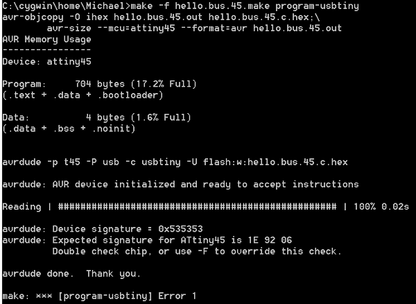
Programming error with one of the nodes.
The master has an ISP header for communicating with a host computer over serial (sending the ID characters to invoke the respective slaves LEDs). It also has a 6 pin ISP header for programming via the FabISP and a 4 pin header for the serial communication with the slaves. The slaves has ISP-header and 4-pin header for networking.
![]()
The nodes ID in the C code.
Things which went wrong:
When programming one of the nodes AVRdude repoted that it had a wrong device signature. So I inspected the board under a loupe and found a small solderbridge between two legs of the ATtiny45. After rectifying that - the programming succeeded. The code sends a command though the network, each node has a different ID and executes only the commands which are ment for it. In the example the master tells the slaves to blink their LEDs. Each board listens to the serial port and reads a "char". Part of the data is the ID. If the ID contained in the data matches that of the node - it blinks the LED. If it doesn't match it just passes on the data for the next nodes.
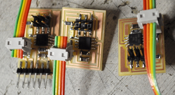
The finished, working network.