Fab Academy 2013 · Michael Hviid Nielsen
Waag Society's Fablab in Amsterdam
· Lecture 13: Output Devices
Lecture 13: April 17, 2013
Assignment: Make a board with an output or output device. Program it to "do something".
Lecture Notes:
What I did:
I made two boards; the single-sided Charlieplexing LED array (hello.array) and the Unipolar Steppermotor Controller (hello.stepper)
Programming the boards were done from the commandline in Win 8 using avr-gcc and the FabISP (here identified as "usbtiny").
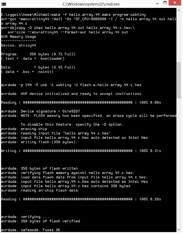
Command prompt: Programming the hello.array
Here is a video (H.264 avi format) of the working hello.array Charlieplexing LED board..
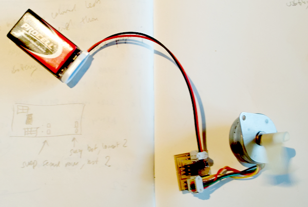
"hello.stepper" doing full steps
Things which went wrong:
Despite considerable effort to keep the red and the green LEDs seperate during stuffing and soldering the hello.array-board, I ended up having two rows mixed up (each one single "line" of LEDs of the same color instead of the intended alternating pattern of red and green. So I had to shuffle those around. I did this very quickly by turning on both our soldering irons - and "grabbing" the LEDs while the solder flowed and lifting them off board with the soldering iron tips - one in each hand. A nice dexterity test. AND I saved several millimeters of desoldering braid...
I also had a nonworking hello.stepper board the first time. The problem was apparently that the wires from the battery were a bit to thick to let the IDC connector close properly.
Things to fix:
I am now looking for a power supply to drive a larger unipolar stepper that I bought (cheap as chips) at the fleamarket at Waterlooplein in Amsterdam. Since the hello.stepper can drive up to 1.7A at 30V - I have to hook up the stepper to a PSU in the Fablab at see and which voltage I am close to but below 1.7A.