Fab Academy 2013 · Michael Hviid Nielsen
Waag Society's Fablab in Amsterdam
· Lecture 10: Input Devices - sensors
Lecture 10: Mar 27, 2013
Assignment: Make a board, Interface a sensor to it, Read it and show the data in any way (LED, interface, serial).
Lecture Notes:
Among the many options for sensors: Switches (momentary or slide), Light sensors (photo resistors or photo transistors or chopped LEDs), Temperature (Thermistors), Sound (using Electret Microphones) the most versatile are measuring capacitance with "step response".
What I did:
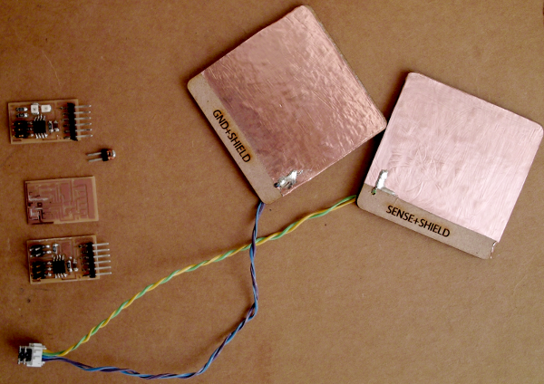
I made two boards; the "hello.reflect" (using an IR LED and an IR phototransistor) and the simple "hello.load" (capacitance). I also prepared sensor boards for the Tx/rx version of capacitance-measurements but I didn't yet produce the board as I got caught up in adjusting the timing of the ATTiny45s.
When making the "hello.reflect" - the photodiodes we had in our inventory was slightly different from the ones in the Fab inventory. I found that it is very important to read the data sheets closely, as even different versions of the same transistors had different pin-outs. I used the OP580 which is matched to the OP280 LED. On OP580 pin 1 is the collector. This pair have the highest sensitivity at 935 nm (visible light is [violet]390-700nm[red] - so infrared, although it can also sense light in the visible part of the spectrum (with reduced sensitivity). Since this is a transistor this naturally affects the handing of the component. The board was, as allways, milled on the Roland MDX-20 using Fabmodules.
The first board I milled was not successfull - it had a clear "gradient" of milled versus unmilled pointing towards something not level with respect to the FR1 stock and the sacrificial layer underneath (another piece of FR1). So I had to remove both - clean the base layer of the modela (an orange piece of plastic) as well as the sacrificial layer and the FR1 stock. Ensuring these where superclean I retaped all of it with Scotch doublesided and removed the board-holder from the milling machine so that I could put pressure on the boards when refitting.
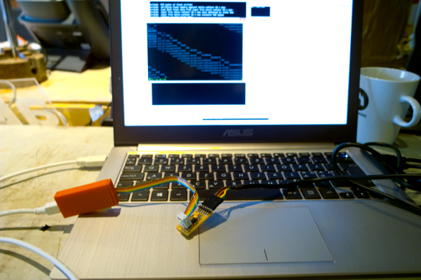
Afterwards, the next boards milled prefectly. However Bas told me that ideally, one ought to run a surface-job after the lower surface has been detatched. After stuffing and soldering the board, I programmed it with the FabISP and ran Neils Python-script for the output. However, something was not right. The Python-scripts halted and exited with faults. Checking a serial monitor it showd garbled output suggesting timing was off. Luckily we just had a short introduction to the oscilloscope by Bas (our "Distributed, local Guru"). So the oscilloscope was put in AC mode (which effectively subtracts the DC component - i.e. the vcc, and only displays changes in the signal). The croccodile clip on the probe was put on the GND (which is thus the ref.) and the probe itself at the signal.
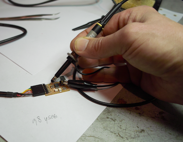
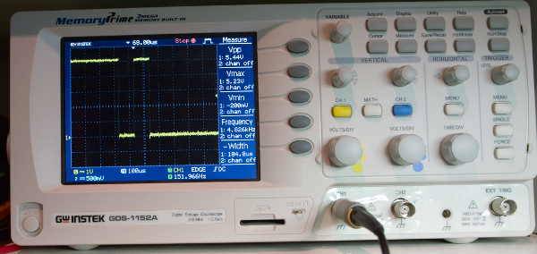
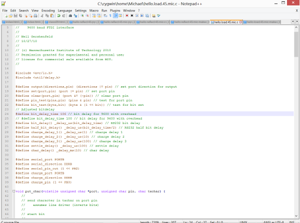
Initially I thought this was the orange wire on the FTDI-to-usb cable - i.e. the Tx (for transmit). Bas enlightend me that this was seen from the computerside of things and that the correct wire is therefore the yellow Rx (receive at computerend - is transmit at hello-board). By measuring the width (time) of one of the short signals (i.e. a single bit) the bit-length was found to be a little off (98.2µsec). The bit-width should be: 1/9600 (the baudrate), which would equal 104 µsec. So the compensation in the software bitdelay should be: 104/98x100 = 106. After adjusting that and recompiling and uploading the resulting width was found to be 103.2 µsec. Using a bit-delay of 107 brings it to 104.8 µsec. So I choose a bit-delay of 106.
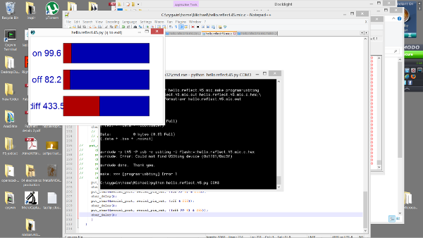
I then did the same with the hello.reflect board and found the measures unadjusted bit-length to be 97.6 µsec and thus used the same software bitdelay of 106. Now both boards function as intended an shows sane values in a communication monitor (trial version of Docklight) as well as behaving well with the Neil's python-scripts.
I learned a couple of tricks during these tests: Testing the hello.reflect board with a camera-phone known to be sensitive to IR. Connecting a jumper across the Tx and Rx lines - sending characters from a serial monitor should echo each character, if not something is wrong.
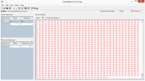
Bas Withagen also showed another trick: Making a small endless while-loop before the main program which just sends alternating 0x00's and 0xFF's (which is alternating high/low bits) checking in a serial monotor is that is also what gets across.
Things which went wrong:
Milling FR1 stock due to some unevenness in the lower layers attachement to the sacrificial board. Solved by detaching, cleaning and carefully reattaching the board-stack.
Things to fix:
Find out how to adjust timing issues by setting the OSCCAL registrer rather than using the run-time variant of using bitdelay.
Make all the hello-boards.
At some point I would like to make all the sensor boards in the "hello-series" just to get a feel of whats possible with each version - because "How can you not come to like those tiny ATs?".