Fab Academy 2013 · Michael Hviid Nielsen
Waag Society's Fablab in Amsterdam
· Lecture 06: electronics Design
Lecture 06: Feb 27, 2013
Assignments: Redraw and modify the Ecco Hello World Board - add at least a LED and a button.
Lecture Notes:
Book recommendation: The Physics of Information TechnologyWhat I did:
The Hello World Board (linked here) consists of an AVR microcontroller and an interface.
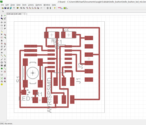
This is the Ecco Hello World Board in Eagle (free software for board manufacturing):
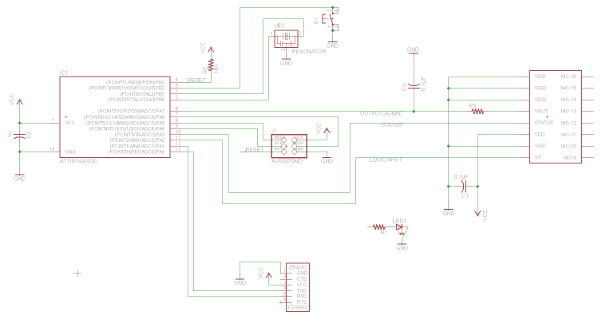
This is the Schematic in Eagle after adding the button, the LED and the current-limiting resistor for the LED
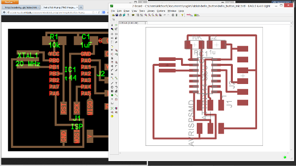
These are the png files which are sent to the Modela (Roland MDX-20) for milling out in FR1 board stock:
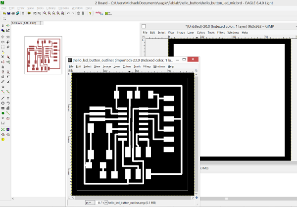
The graphics where exported from Eagle as monochrome images but they have been inverted in GIMP (White is high, i.e. not milled - black is low/milled - the tool cuts on the black side)
The finished png-files which where sent to the Fab Modules are linked here for download: The Board itself, and the png for cutting it out of the stock
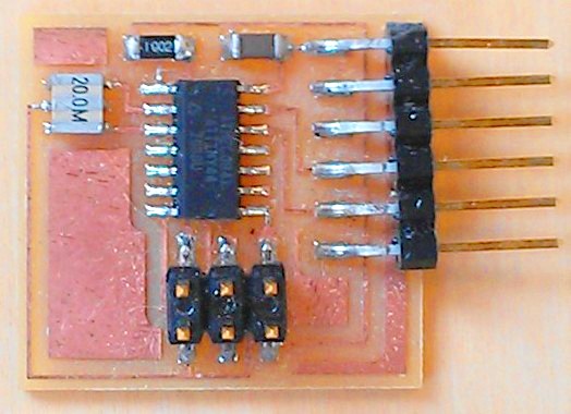
The actual production of the board was rather un-dramatic since we already had "Course 04: Electronics Production" (linked here).
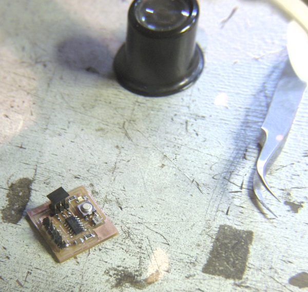
Only tricky part was identifying the handing mark of the SMD LED (See note below in "What I Learned"). The finished board is depicted below.
What I learned:
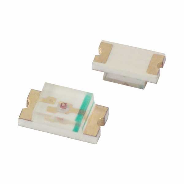
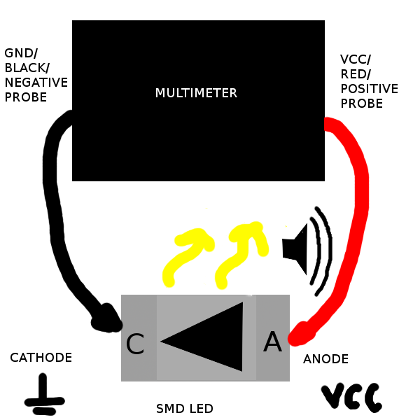
As mentioned above, the only tricky part was identifying the handing mark of the SMD LED. I couldn't find any mark. But under a magnifyer a thin green line was present along the one side of the clear prism covering the diode (not as clear as the one depicted - about as thin as the refracted image of it on the side). I looked at a number of different manufactorers LEDs and it seems that you can pretty much choose your style of marking of either the cathode or anode. What happened to standards? If the LED is of unknown origin another way of determining handing is by using a multimeter with a diodetester with audio signal. Place the diode in any direction near the component placing on the board (but not on any traces or a conductive surface of course). Then put the black probe from the multimeter to the end of the LED closest to your groundtrace and put the red probe to the other end. Now you should hear a sound from the multimeter indicating that the diode conducts current and that it is the right way around (You might even get the LED to light up from the power supplied by the multimeter).
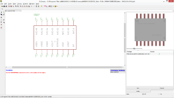
So, with time to spare (a "Fab Academy Rare") I wanted to complicate my Hello World board. So I thought it would be nice to include an accelerometer so the board could respond with 'Hello World' or 'Goodbye World' depending on the direction of movement of the board with respect to the Earth. And of course it would give some insight in dealing with accelerometerdata and the ATTiny. So I checked the Fab Inventory for suitable parts and discovered that the accelerometer which used to be in the inventory was AWOL (it is disontinued by Freescale; the Manufacturer). It has also not been replaced by another accelerometer in the Fab Inventory. Thus let down by bad luck, movements of the markets and the general state of life I naturally turned to our Guru Bas Withagen - as one do in such matters. He told me that eventhough the Freescale MMA1260EGR2 Z-axis accelerometer was no longer available, we still had some lying around. So I trawled the net for an Eagle-file for this component. For some reason I was unable to find it anywhere. It is apparently no longer in the Fab .lbr-files (lrb-files are Eagle component library files). What an opportunity to learn how to add a component to a Library - N'est Pas?
So I found a nice tutorial on this matter on Instructables (here). Being as it is still pretty unfamilliar with Eagle this took some time to get right. You draw the pads and the casing and the "legs"/pins for the component. Then name the pins and draw a symbol for the component then link the pins between the component layout and the symbol and add it to a library. With all this done and the sun descending over the Nieuwmarkt in Amsterdam the sky gradually getting lit from the numerous red lights in the area I started making my new schematic in Eagle of the Hello World board with added LED, button and accelerometer. After adding all the components and thinking about the wiring of them it dawned on me that I was lacking pins on the ATTiny44. The accelerometer uses 3 pins besides power and ground but the Hello World with a LED and a button only leaves 2 pins of the ATTiny44. So the development was halted at this stage. I will probably use the LED as a status LED for the accelerometer and the button for resetting the chip is a fault arises in stead of having LED and button available for programming (not specifically wired to do just one thing). Until now however, it is just an reintroduction of an obsolete parts library file. But all is not in vain because I can now add components to my library-files