Fab Academy 2013 · Michael Hviid Nielsen
Waag Society's Fablab in Amsterdam
· Lecture 05: 3D Printing and Scanning
Lecture 05: Feb 20, 2013
Assignments: Design and print a 3D object - 3D scan an object.
Lecture Notes:
The last couple of pages has had this section empty. I found out that somehow, my notes for the lectures are very close to the lecturenotes we get from Neil Gershenfeld. I have more stuff in my notebooks but I am unsure if anyone will get anything usefull out of them. To make up for this I will expand most pages with a "Class XX Revisited"-section where I can file updates to the same areas as touched upon in class (if Amsterdam Academy gets a 3D scanner for instance - I will revisit the 3D scanning and log my progress).What I did:
I wanted to make an enclosure for my FabISP we made in class04. Its a little too exposed to just pocket
For the design of this I made som rapid (too rapid actually) measurements of the pcb and its protrusions (the mini usb connector and the header-pins especially).
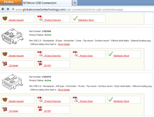
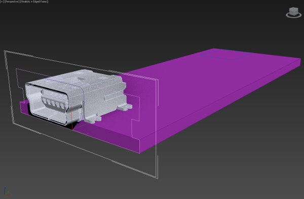
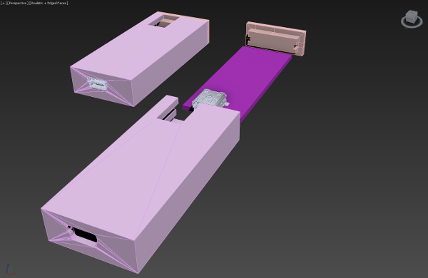
Then I found a lookalike of the miniusbconnector we used at a company who offered 3d models of their components. Its probably not entirely similar but since the usbconnecter itself is standard - this will suffice. I put this on a board in 3DS Max (could have been done in any 3D program). Then I used edges from the model of the usbconnector to build some extrusions I could use as booleans to make cutouts for the usb and the headerpins. I knew from class, that our printer (Ultimaker) uses 0.2mm layerheight in the default profiles. So I made wallthicknesses multiplums af this and added "slipspace" between all surfaces where the printed case would adjoin the FabISP board. I made shure the modelled enclosure and its lid where positioned in a way so that overhangs could be avoided.
So I printed the enclosure and watched with dropped jaw how the printer just continued printing upwards - time to check the notebook. Sure enough a wrong measurement of the lenghth of the FabISP bord. However, all was not in wain, since I could use the failed print to discover that my allowances for movement where to small. Probably due to shrinking of the PLA when it cools. So I made another run for the 3D program and adjusted the measurements and while I where there I also refined the cutout for the headerpins.
![]()
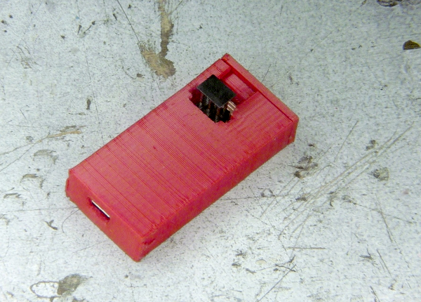
So, in all its glory the new FabISP enclosure was printed and after a slight filing of the areas where I had to remove strings (our default profile for the Ultimaker does not use retraction it seems. Maybe because its a Bowden extruder and the flexibility of the Bowden cable would anihilate any retraction?) the FabISP was lured into its new hideout in bright red PLA.
I probably have to mention that I also spend a little time repairing my FabISP board between these two revisions. When trying to fit the board in the first case I printed I used a common mistake of the car mechanic; "If at first you don't succeed, get a bigger hammer", but this doesn't allways end happily in (and is counter-objective to) digital production. So "suddenly" I lost a capacitor and its solderingpads to a screwdriver that slipped. But since I no longer have big fear of small smd components this was quickly repaired.
For the 3D scanning which was the second part of the assignment I went a little overboard. The intension was to make a small model by hand - then scan it - then print it - then scan that and lastly take the difference between the first and the second scanning which would show loss/gain in the process visually (yes - this is the beginning of a description of another valuable failure).
So I went to an arts store and bought som modelling clay - which turned out to be black. This would have been a natural point in the process to stop and reconsider but since "Persistent Perseverance" is my middle name I went ahead and sculpted this:
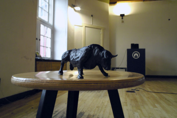
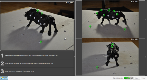
To make a long story short, this turned out to be impossible to 3D scan mainly due to its color and the available lighting. I then marked the model with numbered tacs/pins to help out the scanning and the matching of point in the photos. I could generate only appoximately one third of the mesh with a lot of time spent. Even in the areas where to 3D scan succeeded - I was a bit disappointed with the resolution of the scan. Its easy to get the impression from the textured scan that it is of very heigh resolution but the eye (brain) is deceived because the photo supplying the texture is of cause of heigh resolution but the generated mesh is not. We used 123 Catch from Autodesk to "scan" with. But now I am really interested to see what either a line-laser scan or a structured light scanner can do.
No matter what I may have to paint the model brighter - which will not be easy because its wax. Maybe I will try to heat the surface slightly and then dust it with crushed marble dust (which is a health hazard - so it'll have to wait until I have a vented blast cabinet available).
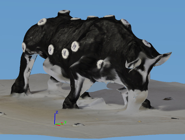
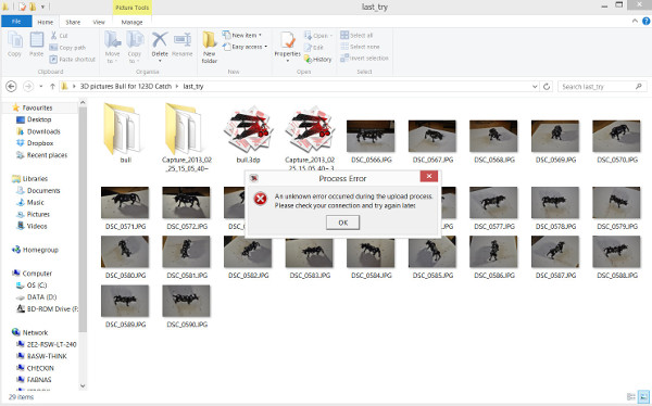
Here is the scanned mess (ups: mesh). The 3D scan is three thirds done but 123D Catch would endlessly fail in creating the mesh itself, printing this error on the screen but each time I got a mail from Autodesk saying that the mesh-generation failed (you can choose to either wait for the output or get the resulting file emailed).
Extra credit
This time there where extra credit for making a 3D scanner. I have not actually done this, but I have a conceptual idea for a simple one which could work - although with many of the same limitations of other ways of doing this.
It consists of an acrylic sphere in two parts, with a collection of circular "groundplanes" which fit inside the sphere and thus leaves a "floor" at a wanted height - so that the center of the object scanned will end up roughly in the middle. Then outside the sphere a camera and a white backdrop arranged to alway be opposite one another. The camera then grabs a frame to begin with, which in software is thresholded to a b/w image (i.e. object/not-object), then traced to a line (i.e perimeter of the object) which is then extruded to the diameter of the sphere. The camera/backgroud-rig then rotates a preset angle and grabs frame 2 - then does the same (thresholding, tracing, extrusion) but makes a boolean not with the preceeding frame etc. etc.
Since each framegrab can be mirrored when seen exactly from the opposite end - we only need a halfdome to fully descripe the (outer!) boundary of an object. Symmetric objects only needs to utilize a quarter of the halfsphere.
What I learned:
I learned that for complex objects and suboptimal lighting - this type of free imagebased scanning is not enough for my needs at the moment. I learned that I would probably need to obtain access to a line-laser or structured light scanner for my 3D scanning needs for the moment. I also learned that the good old saying "measure twice - cut once" works equally well in its digital frabrication rebirth as "measure twice - fabricate once".