Welcome To Zuberi's Final Project Page
For my final project I am made a ball feeder for a ping pong robot. The yellow thing is a ball feed, to push a ball into the launcher of the robot.It has a carriage on the bottom to hold the servo. The arches around it are to hold the ping pong ball because the launcher rotates to shoot ping pong balls with crazy spins and angles, and it doesn't help if the ball falls on the floor before it gets there! You can also see two guide rails which allow only one ball to move forward at a time. The final design was cut from this yellow acrylic.
Watch the feeder in action in this video here!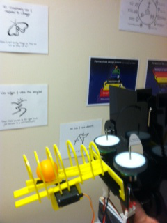
It was drawn in Corel Draw. The ball is taken from a holding container and pushed along by a motorized arm and rolls down into the launcher's wheels. I learned a lot about Corel from the previous projects, so the only tough part about the 2D design was the measuring and having to re cut pieces that broke. I like working with acrylic except for the fact that it is so brittle.
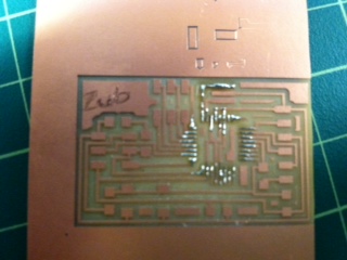
Here is the Arduino board I made myself which is what controls the operation of the motorized arm. You can see in the picture below that I had to splice and connect wires to the ribbons because they fit with the six pin headers. I also did not like the fact that there are no power or ground pins easy to connect to in this design. The program is embedded on the microprocessor and my device receives and sends information back and fourth to the serial monitor in the Arduino IDE.
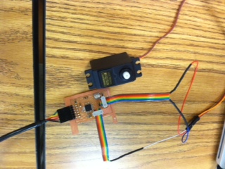
The board was programmed in the Arduino IDE. The "L" shaped arm was designed in OpenScad from the 3D scanning and printing week. The shape of it helps keeps multiple balls from moving down the rails at a time.
In all, I was able to include quite a few of the weekly skills components into my project. From the week of:
Computer Aided Design - I used both 2D program Corel Draw to design the feeder.(yellow acrylic)I found that a difference of .3 mm was enough for press fit joints using the acrylic. Also, here's a great tip: When making a piece with a hole to fit over the shaft of a Servo motor, you can get a good fit by measuring it twice; once straight on to get between the teeth, then again from the side. This allows for the teeth and is not a difficult level of precision for the laser cutter. Use the smaller (straight on between the teeth) measurement to make a circle of the coresponding size, the the side measurement (over the teeth) to make a complex star with 25 teeth(25 teeth was what I counted on my servo, I assume this is standard?). This keeps you from breaking or recutting pieces like I did to try to get a good fit. Another fix is to simply place the piece back in the laser cutter and re-run the print job which will remove very fine layers of acrylic from inside the hole and you can gradually widen it to your liking, although this way is clearly less precise than measuring as I suggested earlier.
The design files are available below.
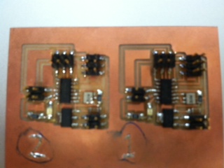
Some of the parts in this file The rest of them hereComputer Controlled Cutting - I cut most parts on the laser printer so that they could be press fit together. Simple and quick, the Epilog became one of my favourite machines to use. The only issue I had here was that sometimes pieces don't cut through all the way so make sure you have the right settings. For thicker materials, higher power and multiple passes might be needed but you should stick to the manual recommendations where possible. Output Devices - I had my electronics board to drive a motor. The servo didn't need to move the full range, only about 80 degrees. So I was able to write a program sending pulses with delays added so that I would hold the position when I needed it to. Electronics Production - I downloaded the arduino board from the fabacademy website. I needed a milled, stuffed and programmed a board myself in the lab. The layout is different than the factory one, but it has the same microprocessor so I can do the same stuff. Electronics Design - I had my electronics board to drive a motor. I also had to design a power supply board to power my prototype board. I ended up making quite a few of these so that others in the lab could use a wall power supply to power their electronics. Here pictured below are the prototype board that I sadly had to abandon because of time constraints. I made this board to drive my servo and communicate over a bus by meshing the two boards into this design. I enjoy designing and building my own boards because I can add new components or layouts however I want. I does help to start from another board design and make changes rather than starting from scratch. Here is the arduino board made in the lab before I stuffed it. As you can tell I used a scrap board someone else had milled on before. We use this practice in Detroit Fab Lab to recycle materials. Embedded Programming - I wrote my own program and uploaded it to my arduino board. Looking at the arduino.cc website was very helpful in helping me to become familiar with the libraries. You have to remember to download the FTDI drivers also so that you can communicate through a Serial Port or SPI. There are a few versions of the arduino but I chose this version because time was short and did not allow much room for experimenting as I had done earlier. I would still modify the board to be more accessible/compatible with other devices like the factory ones are. All the capacity is still there but a more constricted layout in my opinion. I was originally going to use another modified board that I made, but the memory space was mostly used up and the arduino platform and Atmega 168 offers more memory and functionality. Because this was supposed to be part of a whole machine and interface with other devices I decided to go with the bigger better board. 3D Printing - I 3D printed the "L" shaped arm and designed it using OpenScad and MeshLab(to convert to binary format). By using difference of a cylinder and two rectangles I was able to make this piece. The other white piece is a project for another student we added to the tray because the process can be time consuming. I decided to make the part out of tango black so it was soft and stretchy. It kept the necessary shape, but now the hole where it fits over the servo is able to stretch so I eliminate the trouble of cutting acrylic to exact precision of a few tenths of a millimeter; Genius!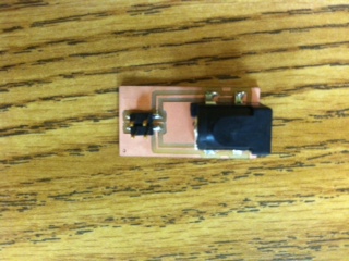
 Back Home