Week 6 Assignments
Table of Contents
Week 6 - Electronic Design
For this week assignment, we have to modify the helloBoard to include a LED and a button. We used Eagle to modify the design, milled the board using Roland Modela and the assambled it.
Some background info
I had some previous experience using Eagle from a workshop offered by Tomás Diez and Yago Torroja on Arduino Shield development a year and a half ago at Medialab-Prado. In the beginning I found the interface navigation utterly confusing, being unable to refocus the board and zooming without too much control. I soon realized I had updated my operating system since the last time I used eagle and that there have been some changes on trackpad usage. I googled it and discovered MacOSX Mountain Lion requieres Eagle 6.0x or higher to offer regular motion gestures. After the upgrade I could control the program in a much more comfortable way.
Back to the basics
To complete this week's assignment I wanted to understand in detail the processor connections, to advance embedded programming contents and also to learn more about the sample board supplied. I located attiny 44 datasheet at Atmel's web site. I discovered at section 10.2.2 how to configure an external clock and I was able to relate it to our setup on Hello Board.
Using Anna's tutorial as a guide I went to through the command line, using some basic commands to add all components to the schematic and to be able to trace the different signal paths.
add led1206
add resistor1206
add 6MM_SWITCH6MM_SWITCH
Always remember to move componets using the cross, otherwise some weird artifacts will happen and parts will move unlinked from the upper level component:

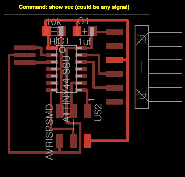
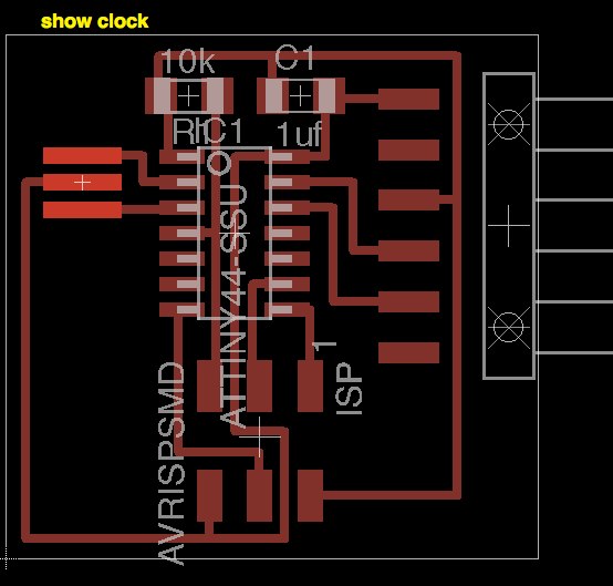
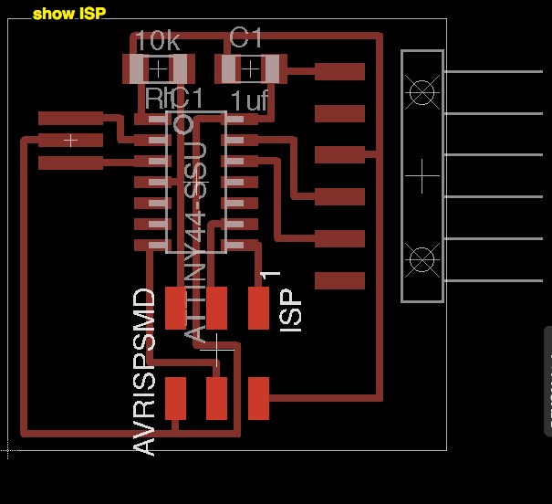
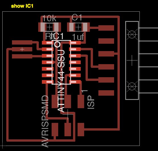
It's possible to use the command show to hightlight components or paths. This command will be also very useful to troubleshoot board problems in the future, following signal continuity on copper paths. I also renamed some nets and components to get a better overview of my board layout.

Net/signal highlighted
show vcc
show clock
show isp
show ic1
I exported the design from Eagle as a monochrome image at 500 DPI to mill it in the Modela. I added some letters to the board using GIMP , but they were quite small and only some of them remained after the milling.
Here is my final version including the surrounding area:
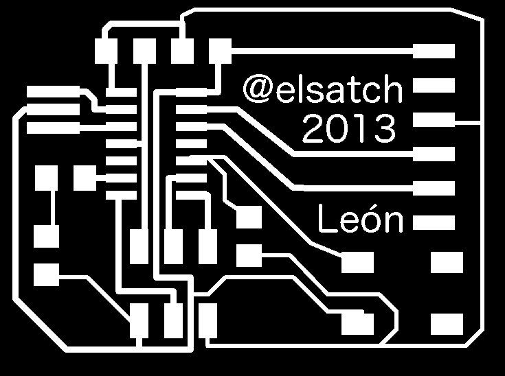

Instead of soldering it using a soldering iron, I tried to learn new techniques like using solder paste, based on this Waag society tutorial. For my final project I need to prepare lots of boards so I'm basically trying to address this problem in every step of the learning process.
A friend of mine suggested me to create an stencil to help me apply the paste in a better way. Using Eagle this is a quite straightforward process:
- Create the desired circuit
- Click on the layer button. Select None and activate back the tCream layer. This layer is just the pads were paste should be applied. (Note: this won't work for boards like the fabispkey were some pads are not marked on the design because they are common ground
- Use the print command to get a pdf with the design. Select no scaling, top left alignment, remove the caption option and print it to file
- Print that file on the Epilog Laser cutter using a heavy paper with this settings: vector only, speed 100%, power 18% and autofrecuency. Remember to check the line width or otherwise you'll get a rastered stencil instead of a working one!
- Stencil is ready to be used!
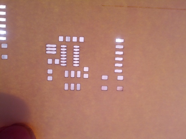
I applied the paste and soldered using a Dremel versatip soldering iron/air I had laying around. The results are quite better than in previous occasions as you can see in this photo:
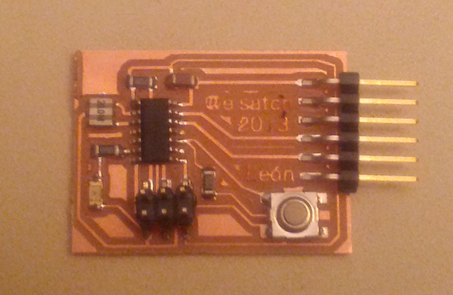
As an additional tip, it's possible to export a Bill of Materials from the top menu, including all parts, positions an orientations. Here is mine, in case you want to replicate this board:
Partlist

Exported from helloEcho.brd at 01/03/13 12:52

EAGLE Version 6.4.0 Copyright (c) 1988-2013 CadSoft

Assembly variant:

Part     Value          Package    Library      Position (inch)       Orientation

C1       1uf            C1206      rcl          (0.58 0.91)           R0
CLOCK    RESONATOR      EFOBM      fab          (0.15 0.74)           R270
IC1      ATTINY44-SSU   SOIC14     fab          (0.45 0.64)           R270
ISP      AVRISPSMD      2X03SMD    fab          (0.5 0.24)            R270
JP1                     1X06-SMD   SparkFun     (1.455 0.66)          R90
LD1                     1206       01_FAB_Hello (0.13 0.315)          R270
R1       10k            R1206      resistor     (0.36 0.91)           R180
R2       499            1206       01_FAB_Hello (0.185 0.54)          R0
R3       10k            1206       01_FAB_Hello (0.72 0.37)           R270
S1                      6MM_SWITCH 01_FAB_Hello (1.165 0.205)         R0
Basic reference commands (from Anna's tutorial)
Eagle has a command line (just start typing commands) - basic commands include:
add = opens up the libraries so that you can add components in Schematic view
always choose the 1206 components
these are the ones that have 12mm x 6mm packages
move = moves an item
net = makes a logical connection
junction = adds a junction
value = addes value to components (i.e. ohm rating)
name = names a component
label = displays the name of a component in schematic view
copy = copies an existing component on the schematic.
rename pieces you copy
route = used in Layout view, this tells you if you need to add a connection (follow yellow lines)
ERC = electronic rules check; this ensures your board will actually work (use in schematic view)
DRC = design rules check (in board view) - keep all the default settings (16 mil is fine); it should display a "no error" message in the bottom left hand corner of the screen
group = groups components in Layout view together; if you right-click, then you can choose Move: Group to move the grouping
rats = in board view, tells you if you have airwires
rip = deletes connections in layout
show = after typing this, select a component to see information about it displayed in the bottom left corner of the screen. Also, if you type show + [name of component] you can see that component highlighted. You can use this to see all the ground traces, for example.
text = allows you to add text to your board. You can also edit the exported .png file in The Gimp to give text and black and white line images. I recommend adding text in The Gimp.)
info = then click on text to get properties of the text