Week 4 Assignments
Week 4 - Electronics Design
Assignment
This week we will learn to use the Roland Modela MDX-20 to create our own PCB's. We will have to create a FabISP and to program it using another FabISP.
Working with the Roland Modela MDX-20
Roland Modela MDX-20 is a wonderful multiuse tool. It can be used to mill several materials and also to scan surfaces using a needle accessory. For this practice we will use the milling feature.
At Fablab Leon, the Modela is connected to a dedicated computer running Ubuntu. Nuria adviced us that there are some issues with the Roland supplied adapter, so we stuck with the current setup. To mill the board we used the fabmodules, already installed.
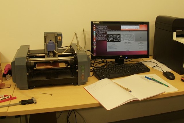
This is the procedure to mill the board:
- Turn on the computer using user: "usuario"
- Turn on the Modela MDX-20
- Open Fabmodules, opening a terminal and executing "fab"
- Select the option From "PNG" To "Roland Modela". Click on the makepngrml option
- Load png file. In our case, the fabisp.png file that contains a black and white drawing of the PCB layout.
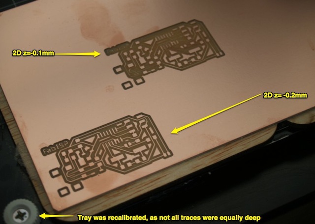
- Select the "Mill traces 1/64" option and verify appropiate parameters are selected. In my case, I used speed=4mm and 2D z=-0.2mm.
- Use double layer tape to secure some spare under the board, and then using double tape again stick a copper layered board to the Modela milling tray.
- Select the 1/64 carbide point. Take care not to handle it by the drill end, as you might get cut.
- To calibrate the Z-axis, push the Up and Down buttons until the motor is about 5 mm over the surface, then using an allen key, let the drill touch the copper gently supporting it with your other hand. Once it's touching the board, secure it away with the allen key.
- If the board is not new, you might have to use the move X, move Y to set the starting point. 0,0 is on the lower left corner. Write down these values as you'll have to use them again if something goes wrong.
- Click on make path, review the board and then click on make rml
- Reset the bus before sending the final model as sometimes some work are stuck. To do it press the "view" plus the "" button at the same time. LED should blink fast for a couple of seconds.
- Press the Send IT! big button and the Modela should start milling your PCB.
Once the PCB is done, it's is necessary to cut the FabISP board from the larger board. To do it, go to fabmodules main window and repeat the procedure, but selecting the "Cut out board (1/32)" option. Select the board perimeter png, and select speed = 0.5 and 2D z = -1.8. Don't forget to input the X, Y starting coordinates and then click on "Make path", "Make rml", "Send IT"
It will take a while to cut the board, as it will need to mill the board 4-5 times to get it clean. Once it's over, you can unstick your board from the Modela.
Things I learned using the Roland Modela MDX-20
This machine is quite unforgiving, and a bit temperamental. We had to disconnect it several times because previous jobs were stuck in the device memory. To make sure you don't damage your previos works, it's best to extract pieces once they are over instead of doing one after another. Press the view button to stop the motor and bring the tray to the front. To reset onboard memory, disconnect the main power supply cable and let it disconnected for a couple of minutes. This time is negliglible compared to having to start again from scratch.
Milling can create a bit of dust, and we were tempted to use a vacuum cleaner, but upon reading the manufacturer manual we discovered it's a bad practice as it could create a fire with the copper particles.
In our first try, -0.1 was not enough to get the FabISP perfect. Once we switched to -0.2 the traces were much more clean.
Mounting the FabISP components
We selected the David variant of the FabISP. Right now, I'm not sure it was the best choice as there are some components that were not available at FabLab inventory and because the miniusb connector was quite hard to solder. I will try to assemble one of the pendrive models in the future to check this out.
This is the BOM for FabISP
| Component | Quantity | Not available in FabLab Inventory |
|---|---|---|
| Resistor 49 Ohm | 2 | |
| Resistor 1K Ohm | 1 | |
| Resistor 0 Ohm | 1 | |
| Resistor 499 Ohm | 1 | |
| Resistor 10K Ohm | 1 | |
| Capacitor 0.1 uF | 1 | |
| Capacitor 18 pF | 2 | * |
| Capacitor 10 uF | 1 | |
| Zener Diode 3.3V | 2 | |
| Cristal 12Mhz | 1 | * |
| ICSP Header | 1 |
It has been imposible to locate those components in Madrid in SMD versions. We asked in Conectrol (one of the biggest ones near the city center) and they neither had them nor had any clue about when they would be available again. Fortunately Nuria and Japi managed to bring some from FabLab Leon right on time to do our practice.
Soldering
This was the first time I tried to solder SMD components. I managed to do it right until I tried to solder the miniusb connector. For the other components, I soldered some tip on one of the pads, then placed the component on top using some pliers and applied heat to fix it. Afterwards, I procedeed to finish the other side. This procedure was obviously not possible on the small pins on the usb port and I ended up with a big tin mess.
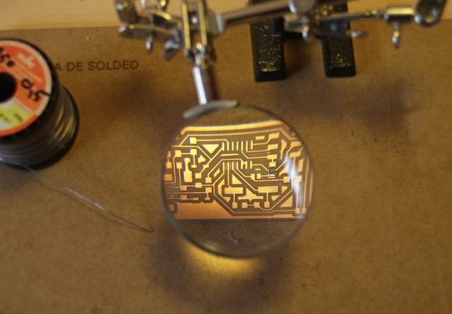
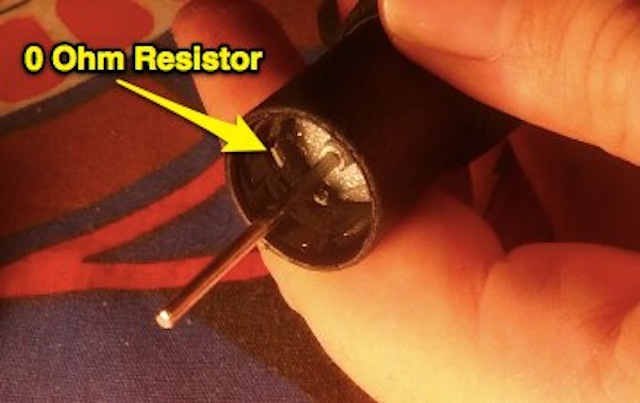
I researched online about desoldering techniques and discovered the vacuum plunger and the desoldering wick. I opted for the vacuum plunger but I discovered it's not the right tool for this size. In this photo you can see the zero ohm resistor stuck in some greasy substance inside:
Fortunately I prepared another additional board at FabLab Leon, just in case. For this board, I decided to use another technique using solder paste (liquid tin in a syrirnge) and hot air, following this Waag Society Tutorial. Instead of the decapating heat gun I used a dremel versatip gas soldering to minimun temperature setting. A friend of mine recommended against it, as temperature is not controlled and suggested just to get a dedicated hot air station and/or a reflow oven. Maybe next time!
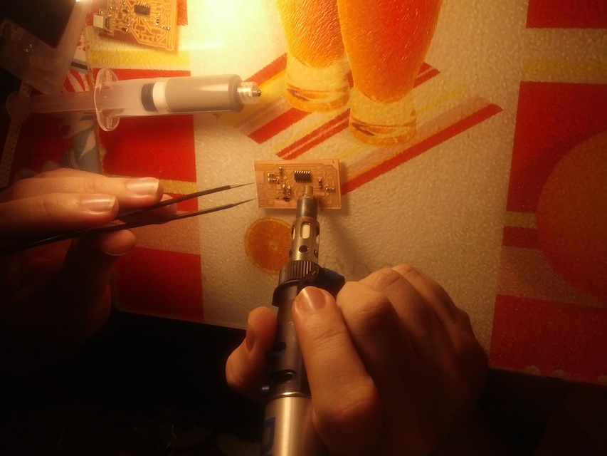
I managed to get all components solded properly and I expect to use this method for the following exercises, except for the pins, that will be soldered using a regular JCB soldering iron.
In the end, this practice was some kind of intensive soldering tools special!
Progamming the FabISP
To program the FabISP we used another regular FabISP from the FabLab. We soldered the jumper J1, to allow it to be programmed.
I already had the CrossPack for Mac installed, so I had required compilers already installed.
We had to swap the crystal from 12Mhz to 20Mhz as that was the only model available. I changed the parameters in the Makefile to reflect the processor model, fuses and clock speed.
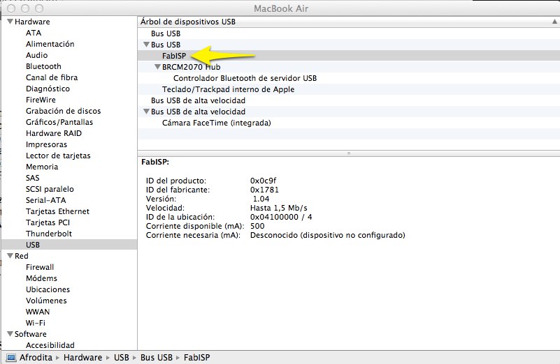
I connected the programmer to the usb port, the flat cable with the red ribbon over the 1st pin. I opened the "About this Mac" report and FabISP was detected as shown in this picture below.
I connected the new FabISB to a USB powered cable to power it and connected the flat cable, with the red cable in the same position.
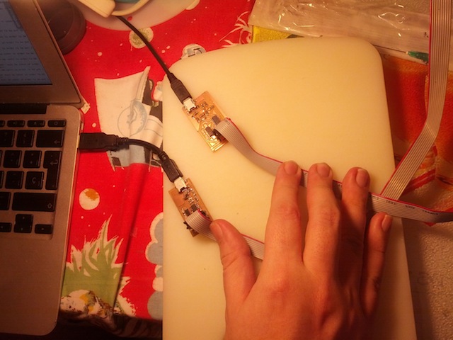
In a Terminal, I just wrote these commands:
make hex make fuse make program
and got this error:
Afrodita:firmware 2 satch$ make program
avr-gcc -Wall -Os -DF_CPU=20000000       -Iusbdrv -I. -DDEBUG_LEVEL=0 -mmcu=attiny44 -o main.elf usbdrv/usbdrv.o usbdrv/usbdrvasm.o usbdrv/oddebug.o main.o
rm -f main.hex main.eep.hex
avr-objcopy -j .text -j .data -O ihex main.elf main.hex
avr-size main.hex
   text    data     bss     dec     hex filename
      0    2116       0    2116     844 main.hex
avrdude -c usbtiny -p attiny44  -U flash:w:main.hex:i


avrdude: error: usbtiny_transmit: usb_control_msg(DeviceRequestTO): unknown error
avrdude: initialization failed, rc=-1
         Double check connections and try again, or use -F to override
         this check.


avrdude: error: usbtiny_transmit: usb_control_msg(DeviceRequestTO): unknown error

avrdude done.  Thank you.

make: *** [flash] Error 1
Conclussion
It seems like my soldering skills need a bit more practice to get it right. I reused several components and maybe one of those was damaged during the process. I will try to create one of the usb keys to get a working FabISP for the other future assignments. I really enjoyed this assignment as I had to learn lots of new stuff. I'm wondering how to make it faster, as my final project involves about 50 boards at each location.
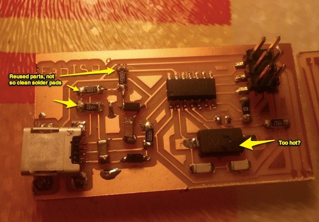
This is my computer showing up the FabISP connected to one of the USB ports
