Week 3 Assignments
Table of Contents
Week 3 - Computer-controlled Cutting
Assignment
This week assigment is to create a press and fit kit using Computer-controlled Cutting, like the Epilog Laser Cutter
Epilog Laser Cutter
Fablab León is equiped with a Epilog Laser Cutter model . It can cut and engrave different materials. The cutting area is 610x305 mm. This area is derived from the larger wood board size of 2440x1220 mm (3 m2). You can cut a larger panel to fit 16 of this smaller panels (2440/4 = 610, 1220/4= 310). The best way to buy wood cheaply is to order a larger panel and have it precut at the factory.
To work with the printer you have to install the driver. This driver can be downloaded from Epilog website. At Fablab Leon, there is a dedicated computer using Windows7, to use with the epilog, that has everything required to print. Let's check the workflow to print something.
- Cutting Workflow
These are the steps required to use the laser cutter to cut something at Fablab León:- Plug an usb pendrive with the required files to the computer connected to the epilog cutter. These can be dxf files for example.
- Open the pendrive using windows explorer. Right click on the file, the expand the "Open with…" menu and select Rhinoceros.
- Press Control+E to select all components in the screen. Then select the stencil width and select "Fine Detail". The laser cutter will only cut areas drawn in "Fine Detail" settings.
- Click the Print icon to open the Epilog driver screen. Click on "Properties" and select the printing area
- On the View section, select the prefered view. In my case it was always "Top" to print the flat views.
- Go back to the main window and adjust the printing area to include all selected parts to print
- Click the Print icon again then "Properties". Dependiing on the material chosen you should select the Speed, Power and Frecuency. For 3,5 mm plywood, I used 20/90/500. It's recomended not to run the Epilog full power unless neccesary, so 90% is chosen instead of 100% by default for all materials.
- Time to move to the laser cutter. Safety warning: Stand in the permanence area in front of printer all times while it's working to spot if there is something going wrong!!
- Open the cover and place materials inside. If plywood is a bit bended, you can try to fix it using the included rulers. Just cover the edges until it's fixed.
- Press the X/Y Off button then Go button. You can move the axis freely to set the new 0,0 position. Take care not to touch the lens or mirrors and always try to move it from the upper bar and the manual autofocus piece to keep it clean for greasy finger marks.
- Turn the Red Laser light on and move it to the desired position. Then push "Set Home" button and then "Reset" button. New X/Y origin is stored.
- On the front screen there should a Job XX Message. When ready to cut, press Reset again to make sure the laser is on the right possition. Turn on the compressor and turn on the filter and then press button "Go".
- Once the laser stops, you can take your creations out. If tha laser is on top of the piece, use the "X/Y Off" then "Go" to move it freely.
- Engraving Workflow
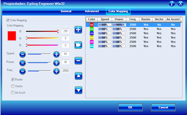
Engraving uses the same workflow as cutting, except you should select other brush width other than "Fine Detail". In the printing properties make sure to select the proper speed/power/frecuency for the raster options. Make sure "Combined" option is selected so you can cut and raster at the same time.There is another option to include several different colored layers with different options called "Color Mapping". This option is available in the Properties section, on the third tab.
We were instructed to use blue color for cutting and red for raster, but after reading this post by Thommas Hopman it seems like the best way to do it is using the black layer (1st) for engraving, then red layer (2nd) for inside cuts and then green (3rd) for outside cuts. In this way you have the least chance of moving the materials. Thanks Thommas for the tip!
Designing objects programatically
To design this week assignment I used OpenSCAD again, for the same reason: easy syntax, enables parametric definition of objects, and multiplatform. As I don't know the exact measures of the net, using OpenSCAD will allow me to adapt it changing the piece areas.
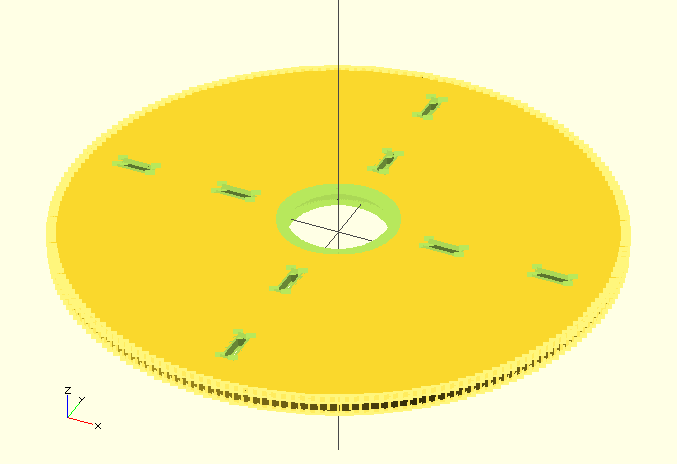
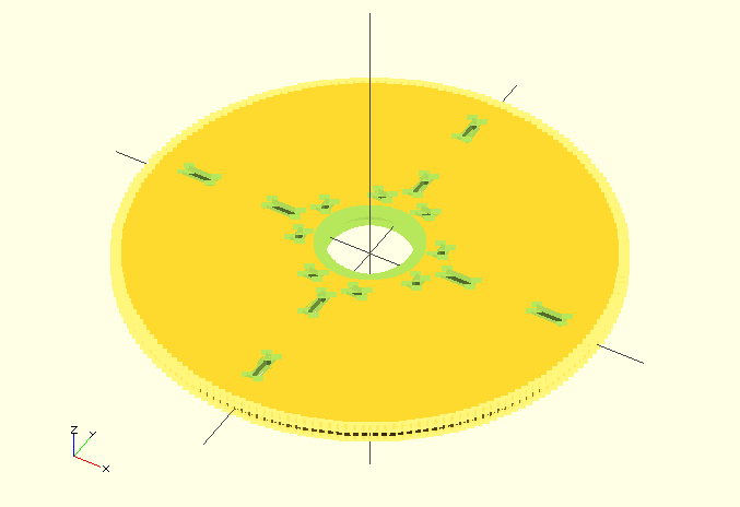
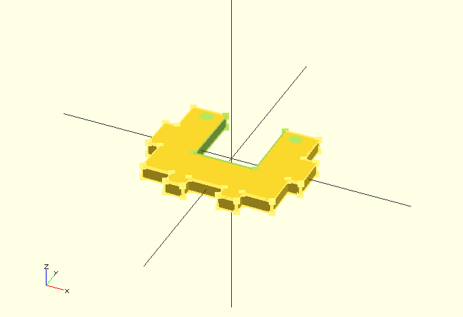
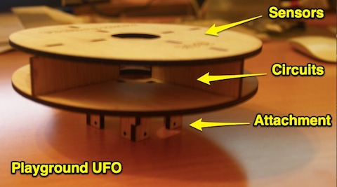
This week assignment involved creating a press and fit kit. Pieces should be able to fit with each other without using any kind of glue or external support. I just decided to model the playground supports using an UFO shape, that could fit in the net and be installed and removed easily using some zippers. The lower part would be the attachment, the middle area would host the electronics and the upper part would show some decorative motives, and leds, sensors in the future.
The main problem of getting a proper press and fit kit is the offset created by the laser cutting itself. If you create a couple of pieces to fit perfectly it wonk work once it's cut. Alejandro created this wonderful kit last year to test it for plywood.
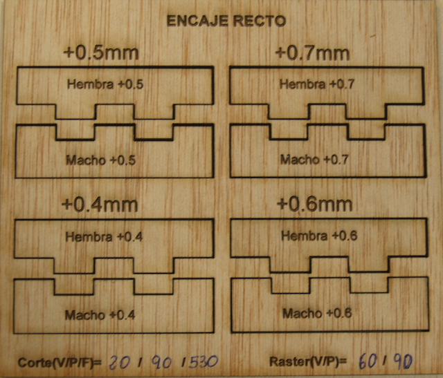
Unfortunately, the offset depends on materials so you have to try it beforehand. Fortunately this can be set as a parameter in OpenSCAD and changed aftewards without changing everything by hand.
In all my pieces the Z-axis height is 3.5 mm because of the plywood used. Given I could not change this parameter, I decided to work on the holes, instead of the other parts.
Here is my first try to determine the offset. In my case, offset = 0.06 mm

Designed parts
- Upper layer
This is the code for the upper layer. This render is made with $fn=200.
- Intermediate bonds
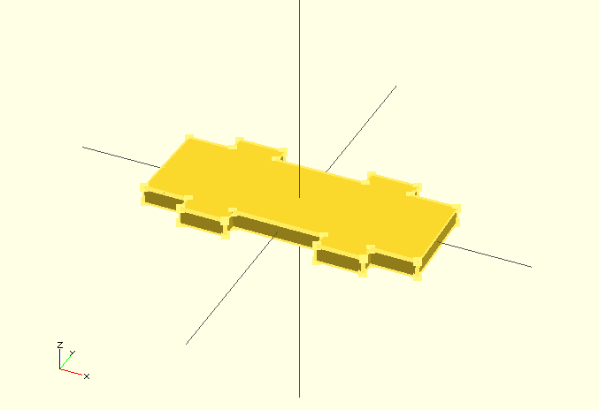
This is the code for the four intermediate bonds
- Bottom layer
This is the code for the bottom layer
- M-Connector for the bottom layer
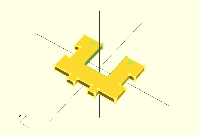
This is the code for the "male" connectors of the bottom layer
- M-Connector for the bottom layer
This is the code for the "female" connectors of the bottom layer
Laser Cutting workflow using OpenSCAD
I never printed before using a laser cutter and I had no idea about the accepted formats, so I had to discover it reading and trying during this week. The final output format accepted almost universaly is .dxf, so I had to figure out how to go from .scad files to .dxf. Here is my workflow:
- Create you piece in OpenSCAD. Use the F5 buton for fast rendering. Tip: In the beginning you should set $fn parameter to a low value, so objects are rendered without too much detail but quite fast. For a circle, it could be created using 20 faces, so the final result is not a circle at all but a 20 faced round shape. For the final renders, I tried and 100-200 range offers good results.
- When piece is ready use F6 button to render and compile. Then on "Design" menu select Export as STL. Select a
- Create a new file and type this code:
projection(cut=false) import("/Route/To/STL/File.stl");
- Press F6 to render and compile. The rendered piece should appear in green.
- Select menu "Design" and then click on "Export as DXF". I use to save files as File2D.dxf
Some notes about this procedure. I decided to create pieces on 3D and then flatten them afterwards. This allows me to manipulate all the pieces in a large sketch in 3D to verify they fit before drawing. I could have used circles and rectangles instead of cylinders and cubes and some of the steps could be ommited.
I discovered it's also possible to run OpenSCAD programmatically, to run all these steps as in batch mode. Here is the information on the OpenSCAD manual and some automation examples using slic3r for 3D printing by PapaGeek. I will come back to this one by the end of the month for sure!
- Printing defects
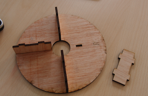
Upon the process I discovered sometimes epilog would not cut a single line on the plywood. Given all my pieces are created from OpenSCAD this behaviour doesn't make sense. I've not been able to troubleshoot this as it happened randomly. Here are some photos. Any ideas?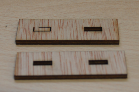
Assignment results
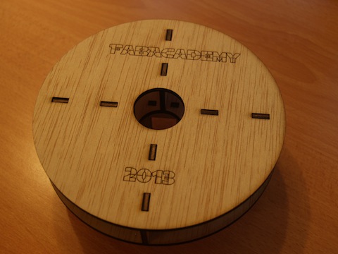
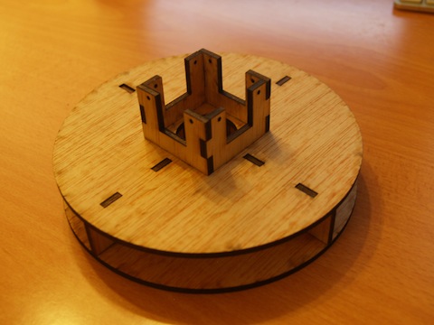
This is the final result for this week assignment: The playground UFO press kit!
Some final words
I really enjoyed this week assignment and I'd like to say hi to people at FPGA-Cafe that shared to joy of this project, with deep laughing and mutual curiosity.
As I final tip, lasers, soldering irons and cnc are fun to use, but always remember to keep it safe! (Like wearing the earplugs in the proper way ;) )
