Week 2 Assignments
Week 2 - Computer-aided Design
Assignment
This week, we had to move from a conceptual view of the project to a computer designed one, using one of several proposed tools. I'm not an expert on computer graphics and my experience is limited to a bit of Photoshop and GIMP for photo manipulation.
Next week, we have to make a press fit kit, and I decided for this week to learn tools that would be useful in general, not just for this week assignment. My goal is try to use only operating system independant open licensed tools for the FabAcademy. In that way I don't have to relearn everything again if I switch computers in the future, neither I will be under vendor lock-in for propietary formats.
Tools I tested
My first option was Inkscape or GIMP. I tried them both but results were very poor given my artistic skills. I could not get the dimensions right and the circles looked either too big or too small. I didn't find a way to define the exact dimmensions for shapes in a precise way other than moving zoom in and out and adjusting the cursor to the grid. After a few attemps I decided to move to the cad programs.
My first choice was FreeCAD, offering a huge array of options and possibilities. I tried the part modelling, based on constraints and I got used to it after a while. The way the reference grid and zoom worked was frustrating, as it didn't not refresh properly. I tried also sketchup, and I had also scale issues with the standing woman as reference and my supersmall pieces.
After a while, I checked the scripting options in python in FreeCAD, as I'm more used to do it programatically, but didn't have time to test it. Back at home, I took a look to a Christmas present book on 3D printing, and discovered OpenSCAD. After a very frustrating day it was extremelly easy to get into it, and I was able to finish my model in under two hours. I imagine there must be clearer ways to represent it, but it's a good beginning on 3D modelling by commands.
OpenSCAD
First thing I had to create was the support mesh, composed of cylinders and spheres on the interesections.
Here is the OpenSCAD code:
$fs=2.0;
distance=100;

module ballRow(height) {
color("black")
        translate(v=[-200,0,height])
                sphere(25);

color("black")
        translate(v=[-100,0,height])
                sphere(25);

color("black")
        translate(v=[0,0,height])
        sphere(25);

color("black")
        translate(v=[100,0,height])
                sphere(25);

color("black")
        translate(v=[200,0,height])
                sphere(25);
}


module verticalRow(rowNum) {
color("red")
        translate(v=[rowNum*distance,0,0])
        cylinder(h=650,r=5,center=true);
}


module horizontalRow(rowNum) {
color("blue")
        translate(v=[0,0,rowNum*distance])
        rotate(a=[0,90,0])
        cylinder(h=650,r=5,center=true);
}

verticalRow(-2);
verticalRow(-1);
verticalRow(0);
verticalRow(1);
verticalRow(2);
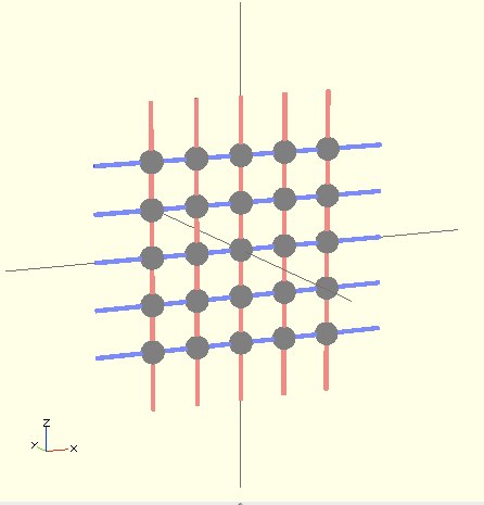
and this is the result:

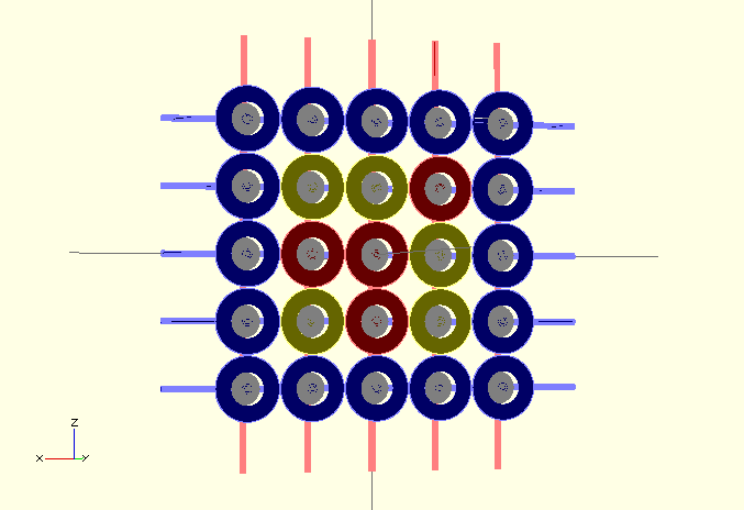
My next step is to simulate the superficial circles that would compose the electronic layer and contain the needed circuits inside. Creating a prototype will be my next week goal.
Here are some examples and the scad file used to generate them

FabModules
I wanted to try FabModules, but there were some errors reported about getting them working under MacOSX 10.8.2. I tried and it worked, so I decided to write a tutorial for my FabAcademy fellows.
Code is cleaner that in OpenSCAD, but much more verbose. References to objects make it simpler to keep things organized logically. Most of the information needed is included into Matt Ketter's tutorial on Designing with Code. I tried to recreate my previous examples without suceess using cadui, following this steps:
- Open a terminal an type: kokopelli. Then press Enter. A python window opens.
- Typing in the left pane makes drawings appear on the right pane.
- Most functions have direct equivalencies in OpenSCAD. I summarize some primitives and functions used.
OpenSCAD Kokopelli Primitives cylinder() cylinder(x0, y0, z0, z1, r) sphere () sphere(x0, y0, z0, r) Functions union() add(part1, part2) difference() substract(part1, part2) rotate([]) several rotate(part,angle) functions translate([]) move(part, dx, dy, dz = 0)
OpenSCAD data was taken from the wonderful cheatsheet created by Peter Uithoven from FabLab Amersfoot and cad ui data from the cad shapes.py file, included in the distribution itself. One of the main differences is the usage of module() in OpenSCAD vs the usage of variable names and addtions in cadui. Check this example:
OpenSCAD
module ballRow(height) {
color("black")
        translate(v=[-200,0,height])
                sphere(25);

color("black")
        translate(v=[-100,0,height])
                sphere(25);

color("black")
        translate(v=[0,0,height])
        sphere(25);

color("black")
        translate(v=[100,0,height])
                sphere(25);

color("black")
        translate(v=[200,0,height])
                sphere(25);
}
cadui
from cad_shapes import *

#render boundaries
cad.xmin = -500
cad.xmax = 500
cad.ymin = -500
cad.ymax = 500
cad.zmin = -500
cad.zmax = 500
cad.mm_per_unit = 25.4 # inch units
cad.type = "Boolean" # Boolean or RGB

sphere_radius=25

ballsRow = sphere(0, 0, 0,sphere_radius)
ballsRow = add(ballsRow, sphere(-200, 0, 0, sphere_radius))
ballsRow = add(ballsRow, sphere(-100, 0, 0, sphere_radius))
ballsRow = add(ballsRow, sphere(100, 0, 0, sphere_radius))
ballsRow = add(ballsRow, sphere(200, 0, 0, sphere_radius))

cad.function = ballsRow
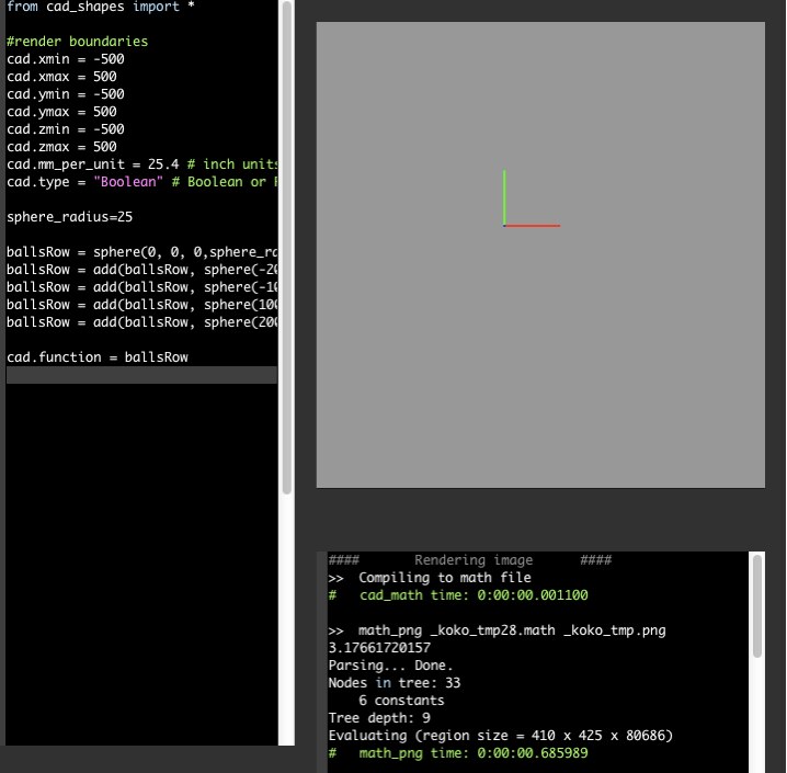
I wasn't able to get cadui to draw the row of balls as in the OpenSCAD example. I will investigate this further next week, to figure out the best workflow to create my pieces in the lab. This is the output I got:
